
Page 21 - Demo
P. 21
process and vital technologies used to achieve the improved FRC performance in HPF and advanced beam-driven FRC states.
3.2 C-2/C-2U Experiments and Main Results
TAE’s research focus and expertise in FRCs were briefly described in the previous section. The C-2 experiment started in 2008 (note that the company’s research in the predecessor A, B, and C-1 devices are omitted here). In the beginning of the C-2 experiment, we mainly focused on a method of generating robust FRC plasmas and optimum operation; when the duration of FRCs began to extend, we shifted our focus sequentially on suppression of magnetohydrodynamic (MHD) instabilities, sustainment of plasma configuration lifetime, and plasma heating by NBI. Improvements of FRC plasma characteristics were successfully confirmed during the C-2 campaign, with further improvements and FRC sustainment appearing possible with a high power NBI system. This motivated an upgraded machine with a brand new NBI system with maximum output power of 10+ MW during the C-2U campaign in 2015. Figure 1 illustrates a schematic of the most recent FRC experimental device, C-2U, and its magnetic field topology, including FRC. The key technologies to achieve HPF plasmas in the C-2 / C-2U experiments are roughly divided into 4 elements: (1) FRC Dynamic Formation, (2) Wall Conditioning, (3) Edge/Boundary Control, and (4) NB Injection. These key components together with the experimental apparatus and main results are described in the following sections.
3.2.1 Experimental devices, C-2/C-2U
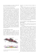
The major improvements of the upgraded C-2U FRC experimental apparatus (Fig. 1) as compared to C-2 are as follows: (i) upgraded and optimized high power NBI system, featuring obliquely angled beam injection, and reduced beam energy; (ii) upgraded end-on plasma guns and concentric electrodes inside divertors for stability control; and (iii)
Fig. 1. (Top) C-2U experimental device, (Bottom) FRC plasma and density contour map of the C-2U device.
optimization of axial magnetic field profiles throughout the machine.
Common features of the C-2 and C-2U devices are described next. The experimental device is approximately 20 m long. The FRC confinement section (metallic container) is installed in the center of the device, while the two formation sections (quartz tube) and adjacent divertors (metal container) are installed symmetrically on both sides of the confinement vessel. Quasi-stationary coils (Fig. 1, DC Magnets) that operate on a time scale sufficiently longer than the configuration lifetime of the FRC’s are mounted throughout the device; the axial magnetic field (Bz) in the confinement section is ~0.1 T and the mirror ratio of the magnetic field necessary for confining the FRC in the central region is about 3–3.5. In addition, there are strong mirror plugs in front of each divertor region that create an axial magnetic field of up to ~2 T. The mirror plugs play an important role in confining the open magnetic field line plasma as well as for the operation of the plasma guns.
3.2.2 Key components to achieve high-performance FRC (HPF) conditions
Here, we would like to explain each of the four major components that are necessary to achieve HPF plasmas in the C-2/C-2U devices.
(1) FRC Dynamic Formation: An important step in the generation of HPF plasma is the production of a good target plasma suitable for effective NBI trapping. The method deployed on C-2/C-2U consists of forming separate FRC plasmas inside each formation region (adopting Field-Reversed Theta Pinch techniques), translating them into the central confinement chamber at speeds of about 250 km/s, and then colliding and merging them into a single FRC state; the final merged state is a suitable NBI target plasma. Typical plasma parameters are: plasma radius rΔφ~0.35 m, length ls~2–3 m, trapped magnetic flux φp~5–7 mWb, electron temperature Te~100–150 eV, ion temperature Ti~500–800 eV, and electron density ne~2–3×10¹⁹ m-3. When the stability controls of the plasma guns and/or NBI are not activated the FRC and its lifetime is mostly determined by the onset and growth of the toroidal n=2 mode, with FRCs collapsing in as short as 1 ms.
(2) Wall Conditioning: In order to increase efficiency and effect of NBI on the FRC plasma, appropriate treatment of the inner wall of the stainless steel confinement chamber (Fig. 1, Confinement Chamber) is required. Since the injected beams interact with neutral particles outside of the separatrix, which causes charge-exchange losses, titanium gettering/coating is periodically applied to the inner wall of the vacuum vessel to reduce background neutrals, improve the wall recycling rate, as well as to further improve the vacuum level and impurity contents. Likewise, applying titanium coating to the inner wall of the divertors results in further improvements in the vacuum level and reduction of impurities in the entire device. Due to this coating technique, the neutral particle density outside of the FRC was greatly reduced, resulting increased NBI into the FRC
2
