
Page 7 - Demo
P. 7
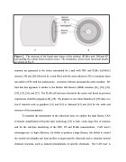
    Figure 2. The structure of the liquid state layers of the solution (FLiBe) with TRUand FP surrounding the central fusion neutron source. The schematics, whose more functional details are shown in Fig. 9.
   neutrons are generated at the center surrounded by a tank with TRU and FLiBe (LiF-BeF2) mixture [19] and [20] followed by a tank filled with the most radiotoxic FPs to transmute them into stable or FPs with less radiotoxicity. A neutron reflector surrounds the entire machine. We find that this approach is similar to the Molten Salt Reactor (MSR) situation [21], [22], [23], [24], [25], [26], and [27]. The FLiBe salt has been selected as the carrier salt based on previous experiences (ALISIA program) [28], [29]. We propose to use either Hastelloy-N [30] alloy or a low-Z material such as graphene [31] and [32] or diamond [33] and [34] for the walls and structure of the transmutator.
To maintain the transmutator in the subcritical state, we employ the high fluence CAN (Coherent Amplification Network) laser technology [35] to both: create large flux of neutrons and for the real-time monitoring of the TRU, FP and FLiBe concentrations. CAN laser’s advantages are: (i) high efficiency; (ii) ability to produce a large fluence; (iii) ability to control the needed wavelengths and laser profiles to target specific chemicals and to stimulate desired chemical reactions, such as induced precipitations of specific chemicals. The CAN laser is
