
Page 13 - Demo
P. 13
Nucl. Fusion 59 (2019) 112009
H. Gota et al
actual field measurements are relatively well matched with field calculations using an eddy-current finite element model (difference within ~10% in amplitude). With a full magnetic field expansion at inner divertor regions, we can achieve a mirror ratio of 30 or larger where the ratio is defined as the confinement mirror field Bmirror over the expanded inner- divertor field amplitude Bexpand (i.e. Rmirror = Bmirror/Bexpand). While the inner divertor fields expand, the mirror ratio for FRC confinement inside the CV (i.e. Rm = Bmirror/B0; B0 is vacuum magnetic field at midplane) is maintained greater than 2.5 throughout the plasma discharge in order to not only assist initial FRC collisional-merging process but also control plasma axial position.
Figure 10 shows an example of two plasma discharges under different machine configurations in operation phases OP1.1 and OP1.2: C-2U-like machine configuration (no inner-divertor magnetic-field flaring) with negatively-biased edge control from outer divertors in OP1.1 (shot #104989), and flared inner-divertor field configuration with positively- biased edge control from outer divertors in OP1.2 (shot #107322). Note that NBs are injected for longer than FRC plasma lifetime in both cases. Time evolution of the electron temperature profiles, measured by midplane time-resolved multipoint Thomson scattering system [31], for those shots are also shown in figure 11, both of which exhibit a hollow radial profile as anticipated by the FRC structure. Under the C-2U-like machine configuration using only outer-divertor edge biasing/control, FRC plasma has successfully lived up to 8+ ms which is long enough to move on to the next operating phase (meaning that OP1.1 to OP1.2: edge biasing/control primarily from inner divertors with magnetic field flaring). In those long-lived FRC plasma discharges, a micro-burst type of weak/benign instability induced by injected fast ions has been observed [30], as previously seen in C-2U [46]. We have recently begun a new operating mode in OP1.2, in which extensive optimization processes have been executed both manually and with Google’s optimization tool/algorithm [40] on many C-2W subsystems such as pulsed powers, magnets including fast-switching coils and formation DC coils, edge biasing/control systems and wall conditioning, which resulted in relatively good initial FRC plasma states with higher elec- tron temperature as seen in figure 10 (shot #107322). In this inner-divertor operating mode with magnetic field flaring (OP1.2), FRC plasma duration is not quite as long as outer- divertor operating mode (OP1.1) because the transition of the edge/boundary control regions from outer to inner divertors is not yet adequately performed; this might be due to a lack of stabilization effect and increased parallel transport property by unfavorable open-field-line plasma conditions during the transition of edge control areas. However, this result of early experimental campaign in OP1.2, indicating high initial Te state as well as increasing the temperature for a short period of time around t ~ 1–2ms as can be seen in figures 10 and 11(b), is quite encouraging and promising result in this opera- tion phase before NB input power is increased in operations phase 2.
(a)
(b)
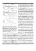
Figure 9. Plasma rotation and velocity measurement by ion Doppler spectroscopy: (a) rotation velocity evolution at various impact parameters of viewing chords in the cases with and without edge biasing, in which only a half of the chords are shown for simplicity and also error bars are not included because they are within a few km s−1 level; (b) peak rotation velocity at various edge-biasing operating conditions where total biasing current is estimated from biasing power supplies on both sides, and plots are averaged over several similar shots.
can be seen in figure 1(c). In the early C-2W experimental campaign the machine was operated as C-2U like configura- tion (in OP1.1), meaning no magnetic field flaring at inner divertor regions as shown in figure 1(b), to produce long-lived stable FRCs whose duration has to be long enough in order to adequately transfer edge biasing/control regions from outer to inner divertors. Note that magnetic field switching time (from straight field to flared field configurations by reversing a cur- rent direction in the fast-switching coils that typically starts at around t ~ 0 or slightly earlier) inside inner divertors is about a few milliseconds so that achieving FRC plasma duration of ~5ms or longer in OP1.1 was one of our key early scientific milestones. In order to verify the inner-divertor magnetic field profile as well as its time evolution during the field flaring, a custom magnetic probe array was temporally installed and scanned around inside the inner divertor. It was found that the
13
