
Page 4 - Demo
P. 4
Nucl. Fusion 59 (2019) 112009 H. Gota et al
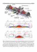
Figure 1. (a) Illustration of the C-2W experimental device, Norman. Sketches of FRC magnetic field-line topology and density contours in color, using 2D multifluid force-balanced equilibrium calculation performed with the LReqMI equilibrium code, in (b) operations phase 1.1 (OP1.1)—outer-divertor operating mode and (c) operations phase 1.2 (OP1.2)—inner-divertor operating mode with flared magnetic field.
There are complex magnet and control systems on C-2W that have much more operating flexibility and reliability com- pared to the previous C-2U device. Figure 2 shows a layout of the C-2W magnet systems, which includes the confinement equilibrium and mirror coils, saddle and trim coils, in-vacuum
fast-switching coils, DC formation coils, and mirror plug coils; the coil configuration is symmetrically arranged rela- tive to the machine midplane (z = 0). Note that FRTP forma- tion coils (pulsed-power systems) are not shown in figure 2 for simplicity. A set of DC magnets and power supplies,
4
