
Page 3 - ntegrated diagnostic and data analysis system of the C-2W advanced beam-driven field-reversed configuration plasma experiment
P. 3
10K114-2 Thompson et al.
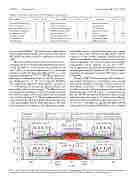
TABLE I. Comparison of major C-2U6 and C-2W diagnostic suite components.
Rev. Sci. Instrum. 89, 10K114 (2018)
FRC core/SOL
Combined B-dot/flux loops Linear array B-dots
Three axis Mirnov probes External flux loops/B-dots Interferometry chords Polarimetry chords
TS time points TS radial points
C-2U C-2W
FRC core/SOL
High speed cameras
Survey spectrometers Diagnostics neutral beam CHERS and FIDA systems Bolometer channels
Neutral particle analyzers DD fusion product detectors Microwave reflectometer
C-2U C-2W
2 2 3 5 0 1 3 4 344 640 2 2
3 5 1 1
Plasma jet
Interferometry chords TS time points
TS radial points Doppler spect. chords Divertors
End loss analyzers Interferometry chords High speed cameras
C-2U C-2W
1 5
0 4
0 5
3 3 C-2U C-2W 2 16
0 5 0 2
0 22 17 22 14 64 21 152 10 14 4 14 2 35 9 16
10
FRC core and SOL electron density ne profiles are pro-
vided primarily by a 14 chord far infrared (FIR) interferometry
system operating at λ = 433 μm near the mid-plane (z = 0
11
μm) system deployed on C-2U.
the types listed in Table I.
physics studies and the plasma active control system, which will stabilize the plasma while Be is ramped up to as much as 3 kG.
field in FRC plasmas, so the Faraday rotation angle is small
(<0.5◦ in some cases). Therefore, the FIR system is built on
a massive (∼30 ton) structure completely isolated from other
equipment to minimize vibrations, which are the main cause
This extensive array supports both
cm).
sensitivity over the 10 chord mixed FIR and CO2 (λ = 10.6
Other advanced
This is a substantial improvement in resolution and
high-fidelity reconstructions of the core and SOL density pro-
file, which peaks at ne ∼ 3 × 1013 cm−3 in typical C-2W FRCs.
Two single-chord dispersion interferometers operating at
λ = 1064 nm and 532 nm provide additional density data
during FRC translation and merging.
14
The FIR chords are
also designed for polarimetry with seven chords traversing
the vessel at an angle of 90◦ to the machine axis and another
◦
seven chords at an angle of 75 . The perpendicular chords are only sensitive to Bθ , while the angled beams are also sensitive to the main magnetic field Bz of the FRC plasma. The peak of plasma density corresponds to the minimum of magnetic
12,13
The FIR system provides
FIG.1. IllustrationofC-2Wtakenfromequilibriumsimulationsshowingtheoverallplasmaandmachinegeometry.Caseswithbothstraight(a)andexpanded (b) magnetic field lines in the inner divertors are shown. Typical plasma parameters for the C-2U-like configuration (a) are listed at the top.
11
backscattering system deployed on C-2 and C-2U5,15
of noise in the signal.
will be upgraded to also perform cross-polarization scatter-
The microwave reflectometry/Doppler
16
The main C-2W Thomson scattering (TS) system gener-
ates electron temperature Te measurements of the core and
SOL near the mid-plane at 16 radial locations and up to 35
17–19
times during a 30 ms shot. Thus, a full time history of
T e , which would have taken many plasma shots to build up with the two pulse C-2U TS system,19 is recorded on every shot of C-2W. The system routinely provides both the electron temperature (detection range 10 eV–2 keV) and an indepen- dent electron density measurement (detection range 1 × 10¹² –2 × 1014 cm−3) of the FRC core and SOL. The main C-2W TS system consists of a commercial Nd:YAG laser at λ = 1064 nm
ing off magnetic field fluctuations on C-2W.
diagnostics for measuring the internal FRC field are under development.
