
Page 3 - Overview of TAE technologies’ HHFW project on LAPD
P. 3
desired value of |n//|, for example |n//| = 10 for wave’s good penetration into FRC plasma, a low phasing is needed; however, low relative phasing can cause significant impurity generation in high power operation. Comparing with other relative phasing, dipole phasing has a better heating efficiency but its |n//| is too large. Therefore, in order to use diploe phasing while maintaining |n//| = 10, wave frequency has to be increased. Slots at septa or sidewall can increase wave’s power coupling to plasma but they can also cause the mutual coupling between straps, which may make impedance matching more difficult. As shown in Fig. 1(a), slot length has no effect for the spectrum at dipole phasing, but it has significantly more effect for 300 phasing, as indicated in Fig. 1(b). MWS calculation of mutual coupling at 10 MHz indicates >4% coupling with 105 mm long slots, <3% coupling with 60 mm long slots. For antenna operation above 10 MHz, incorporating a nearest neighbor decoupling network into the feed and matching network is necessary.
A broadband matching network and decoupler are currently under design by ORNL RF group. This matching network allows antenna operation at 10 MHz and 30 MHz for arbitrary phasing, over a wide range of loads (from vacuum to several Ohms).
Antenna mechanical design has been performed by ASIPP based on the geometry parameters through 3D EM MWS calculation, and it took less than 3 months to complete this mechanical design work. The outline of antenna structure inside and outside LAPD vacuum vessel is shown in Figure 2(a). Antenna has been fabricated at the workshop of ASIPP in Hefei, China, and it has been delivered to UCLA and installed on LAPD on schedule. Figure 2(b) is the photo of phased-array antenna recently installed on LAPD machine. In summary, TAE’s HHFW antenna for LAPD is an international, multi-institution, well-coordinated, and successful project; the construction of a high quality 4-strap antenna has been completed on time (less than a year) as planned.
PRELIMINARY RESULTS OF FAST WAVE PROPAGATION STUDY
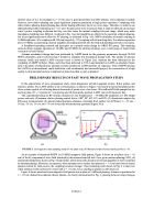
In the experiments of wave propagation study, main diagnostics include Langmuir probes, B-dot probes, and emissive probes. The LAPD utilizes a x-y (vertical plane, as shown in Figure 3 (a)) and x-z (horizontal plane) probe drive system capable of collecting data at thousands of points over a few hours. Wave B and E fields sampled in x-y and x-z plane (31 × 31 points) at 1 cm spacing and 10 shots/probe position. LAPD can run 24 hours per day.
The experimental setup for RF systems includes (1) four broadband (1 – 35 MHz) RF amplifiers at 1 kW output power each unit; (2) antenna relative phasing control driver (1800, 900, 600, 450, and 300); (3) directional couplers for RF power measurements; (4) antenna radial positions (distance of antenna front surface to LAPD axis: r = -35 cm, - 30 cm, -25 cm, -20 cm, and -15 cm) along edge plasma density gradient (Figure 3(b)).
1013
12
D2
Positions of Ant-e2nn0a
LaB6 -25 Source
BaO Source
-35
10
(a)
FIGURE 3. (a) Diagnostics data sampling setup for x-y plane scan; (b) Measured radial electron density profile (z = 0).
As an example of measured HHFW (at 10 MHz) magnetic field pattern, Figure 4 shows an x-y plane (at z = -16 cm) of the Bz component of wave field launched by the antenna from left side. For a given antenna phasing (1800), all measured field patterns shown in Fig. 4 look similar, which means the direction of wave propagation is well-controlled by antenna phasing. Moreover, as expected, when antenna moves further into plasma (r = -15 cm) and close to denser plasma created by LaB6 source, the coupling becomes stronger. One promising result shown in Fig. 4 is that even when antenna is fully retracted to vessel wall (r = -35 cm), wave coupling to plasma is still observed.
Figure 5 shows measured wave magnetic field pattern in x-z plane at 5 different phasing. Antenna is positioned at r = -25 cm; dashed lines indicate denser plasma. As clearly demonstrated in Fig. 5, phasing between straps changes
070002-3
(b)
