
Page 2 - Hybrid MHD Model for a Driven, Ion-Current FRC
P. 2
magnetic field. For simplification, the launcher’s toroidal angle φ (measured at the source from the R-vector through the source) is set to zero (rays are launched in X-Z plane) throughout the simulations while the poloidal angle θ (from x-axis rotates clockwise in X-Z plane) is varied during the process of optimizing the O-X-B mode conversion.
(a) (b) FIGURE 1. (a) The top view and (b) the end view of the C-2 device with an available port for EBW heating.
(a) (b)
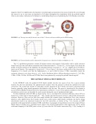
FIGURE 2. (a) Electron density and (b) characteristic frequencies as a function of radius at midplane (z = 0).
The C-2 equilibrium parameters contain 2D plasma density and magnetic field profiles with a radial extension from Z-axis up to the wall and an extension in the Z-direction from Z = -3.0 m to Z = +3.0 m. Figure 2 (a) shows the profile of electron density at the midplane; the maximum density is around 3.2 × 10¹⁹ m-3, slightly above 50 GHz O- mode cut-off density. The separatrix is located at R = 34 cm. Figure 2 (b) shows radial profile of the characteristic frequencies. It is clearly seen that the fundamental fce is just a little bit above 2 GHz; meanwhile, inside the
separatrix, plasma is over-dense where fpe ≫ fce. In the simulations below, different heating scenarios (f = 2.45 GHz, 5 GHz, 8 GHz, 18 GHz, 28 GHz and 50 GHz) have been optimized by varying the poloidal launch angle θ.
THE GENRAY SIMULATION RESULTS
In the GENRAY code, the optimal O-X-B launch module involves two types of run. For a given antenna location, the first run determines the optimal launch angle(s) from the antenna to obtain the optimal O-X mode conversion. The second run consists of launching a power spectrum of the O-mode rays from a specified launch location, generally using launch parameters determined in the first run. The power is transferred to the plasma in accord with the Mjølhus formula [5] for the transmission coefficient. A cone vertex spatial coordinate is used in the calculations, and six rays are launched for each scenario during the scan of optimal poloidal angle.
For the simulations with 2.45 GHz, as shown in Fig. 3 (a), a very high O-X conversion efficiency (above 90%) is found over a wide range of launch angle (410 – 480), and the injected microwave power is almost fully absorbed by electrons. However, there are two facts that would exclude this scenario from consideration. First, since electron density is only slightly below the O-mode cut-off over a wide region, small density variations can lead to strong deterioration such as an undesired location for the X-B conversion, as shown in Fig. 3 (b). Second, an EBW generated at the upper hybrid resonance (UHR) would have to propagate a long distance across the scrape-off layer (SOL) before it reaches any fce harmonic layers. Due to low electron temperature in this region (tens of eV), strong collisional damping of the EBW power occurs [6] soon after the X-B mode conversion (Fig. 3 (b)), leading to a
090008-2
