
Page 3 - Development of a magnetized coaxial plasma gun for compact toroid injection into the C-2 field-reversed configuration device
P. 3
11D406-3 Matsumoto et al.
Rev. Sci. Instrum. 87, 11D406 (2016)
FIG. 3. Relationship between electron density and velocity in the drift tube. Ek is the kinetic energy from density and velocity.
D. Field penetration
The glass tube region has a transverse magnetic field of ⇠1 kG, which is comparable to the C-2U confinement axial magnetic field. The transverse magnetic field is constructed as a pair of square coils, which is similar to the Helmholtz coil. The magnetic field extends along the machine axis for ⇠70 cm from the entrance of the glass tube. The FRC separatrix position in C-2U is situated about 40 cm from the confinement- vessel wall. The virtual FRC separatrix position on our test stand is around the middle of the transverse coil, as shown in Fig. 1. The schematic end-view of the diagnostic setup on the glass tube is illustrated in Fig. 4. The collimated fibers are aligned along y-axis at intervals of 2.5 cm and can move along the machine axis ranged from 39 to 62 cm on the glass tube; therefore, this fiber array can measure upward motion and downward motion of the CT/plasma at each position to observe its trajectory. Usually, the CT inside the transverse magnetic field gets deflected due to the external magnetic field and the current of CT interactions, or polarization of plasma.6 The CT pushes aside the magnetic field when it penetrates into it. So, we installed the magnetic probe array outside of the glass tube at intervals of 10 cm along the machine axis, as shown in Fig. 4, to measure the fluctuation of magnetic field when CT penetrates. These probes can also measure the transverse magnetic field.
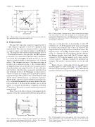
Figure 5 shows the time evolution of each magnetic probe signal as well as the vacuum field distribution along the ma-
FIG. 5. Time evolution of magnetic probe signals obtained from the upper array (red) and the lower array (blue). Left figure shows vacuum field at probe position before CT penetration (at t = 0). Right figure shows time evolution of field fluctuations ( Bx) from each probe; the dashed lines connected around the initial peak of fluctuation.
chine axis over the glass tube, as shown in Fig. 4, before CT penetration at t = 0. Both magnetic probe arrays are arranged at positions away from the axis of the coil; therefore, the magnetic field at the probe position is weaker than on axis. The typical position of C-2U FRC separatrix radius rs is depicted in Fig. 5 to illustrate the CT penetration; the line indicates the distance from the vessel wall. The CT velocity can be estimated by TOF from the magnetic probe arrays, and the velocity reached to ⇠100 km/s as indicated by dashed lines in the figure. This speed is consistent with the one from the drift tube.
Figure 6 shows a relationship between magnetic probe and fiber signals. As can be seen in Fig. 2(d), the CT starts to travel into the glass tube region around t = 30 μs. When the CT penetrates the transverse magnetic field, the CT excludes the
FIG. 4. Schematic end-view of diagnostics setup on the glass tube. The mag- netic probes measure the magnetic field in the x direction. The collimated fiber array measure the CT position along the y direction.
FIG. 6. Relationship between axial magnetic probe array (markers) and radial collimated fiber array (contour plot). Penetration of CT starts around 30 μs. Scanned area by fibers is from 39 cm to 62 cm in z direction and ±8.75 cm in y direction.
