
Page 5 - Compact Toroid Injection Fueling in a Large Field-Reversed Configuration
P. 5
082512-5 Lau et al.
Phys. Plasmas 24, 082512 (2017)
decreases until a jump up to a similar frequency which trends downward again. This jump is associated with a change in the poloidal mode structure from odd parity about the mid- plane to even parity.
A stability threshold is found at drive strength around jsim 3–5 for longer wavelengths as seen in Fig. 3, which is comparable to jexp 3.9 as measured in experiments. Shorter wavelengths are found to have lower stability thresholds.
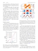
As seen in the mid-panel of Fig. 4, the mode structure in the SOL spans the field-line length is dominated by poloidal mode numbers m 1⁄4 1 with smaller components of m 1⁄4 0 and m1⁄42 (where the poloidal direction is the horizontal axis). The central location of the mode can be explained by the effects of gyro-averaging and by the behavior of the resonant particles. As seen in Fig. 1, kf is lower at the mid-plane (Z 0) and higher at the axial ends (Z 62) by more than a fac- tor of two, leading to a weaker gyro-averaging effect in the central location. The dominant particle resonance is due to barely trapped electrons in the central location, as seen in the figure-8 structure in the vk h phase-space plot in Fig. 4 (detailed in Sec. IV B).
B. Particle resonances
The square of the perturbed distribution functions df2 is plotted in the plane of energy (E/T) vs pitch angle (lB0/E) for both species in Fig. 5 for the kfqs1⁄44.1 (n1⁄475, g1⁄41, j 1⁄4 6.7). For this instability, electron resonance is more important than ion resonance (dfe2 > dfi2). The resonant ion motion is the drift due to rB and curvature, as shown by the curves in the upper panel of Fig. 5. More importantly, the resonant electron motion which drives this instability is shown to be the bounce motion of barely trapped electrons, as shown in the lower panel of Fig. 5.
FIG. 3. Growth-rates (c) vs drives (j) for unstable collisionless SOL modes for g 1⁄4 1 at various length-scales are plotted as solid lines. The unstable col- lisional kfqs 1⁄4 16.4 mode for g 1⁄4 1 is also plotted as the dashed line. The threshold is found to be lower for shorter wavelengths.35 The growth-rates for kfqs 1⁄4 1.37 (blue) without FLR effects (þ) and without rB effects (x) are also plotted for comparison.
FIG. 4. The top panel shows the vk h phase-space of the electrons with the color representing dfe2. The middle panel shows the electrostatic potential in the f – h plane for the case of kfqs1⁄44.1 (n1⁄475, g1⁄41, and j1⁄46.7). The bottom panel shows the potential along the poloidal direction for f 1⁄4 0. In addition, the magnitude and the radial gradient of the magnetic field are shown as the blue and purple curves corresponding to the left and right axes, respectively.
The electrons can be separated into three groups: locally trapped electrons, globally trapped electrons, and passing electrons. In the SOL, the geometry is such that there are two small magnetic wells and an overall large magnetic well as seen in the blue curve of the bottom panel of Fig. 4. Locally trapped electrons are bound within the two smaller magnetic wells. Globally trapped electrons are bound within the overall larger magnetic well. Passing electrons are able to freely stream through the magnetic well in the periodic domain. The boundaries of these trapped-passing regimes are denoted by the arrows in Fig. 5. From the perturbed dis- tributions of the electrons in Fig. 5, it can be clearly seen that the mode frequency is aligned with the bounce fre- quency of the barely locally trapped electrons at lB0/E 1⁄4 1. This resonant motion can also been seen when the perturbed electron distribution function is plotted in phase space (vk vs h) as in the top panel of Fig. 4. The figure-8 shape highlights the motion of the barely trapped electrons moving back and forth within the magnetic well.
Further evidence of the importance of this bounce motion of the electrons in driving this instability is seen from the case of purely density gradient driven instability (g 1⁄4 0) and the case of ion-temperature and density gradient driven instability (gi 1⁄4 1) (detailed in Sec. IV C).
C. Stabilizing mechanisms
As in the core, the stabilizing influences of the finite Larmor radius (FLR) and magnetic well (negative rB) are explored in the SOL by turning on and off these effects in
