
Page 2 - Measuring dynamic fast ion spatial profiles with fusion protons in the Madison Symmetric Torus
P. 2
10I104-2 Magee et al.
Rev. Sci. Instrum. 89, 10I104 (2018)
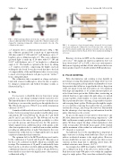
FIG.1. CADrenderingsillustratehowthelineofsightcanbeadjustedwith a linear feedthrough without breaking vacuum. The collimation angle can be changed by swapping exchangeable collimators mounted to the end of the collimation tube (inset).
a 2′′ diameter sleeve, as illustrated in the inset of Fig. 1. The fine collimator (pictured left) is made up of approximately 200 tubes with 0.12′′ OD and 0.01′′ wall thickness cut to 3′′ lengths to give a collimation angle of 2◦. The coarse collimator (pictured right) is made up of 10 tubes with 0.5′′ OD and 0.035′′ wall thickness cut to 2′′ in length for a collimation angle of 13◦. The bundle is captured in the sleeve by slitting a 2′′ stainless steel tube, compressing the bundle, and tack welding the slit closed. It was discovered that due to the lack of compressibility of the small diameter tubes, it is necessary to insert a few larger diameter roll pins to prevent “rattlers”9 from coming dislodged.
The collimation tube is mounted on a hinge and articu- lated with a linear feedthrough to allow the line of sight to be changed continuously and without breaking vacuum, as illustrated in Fig. 1.
C. Foils
It is necessary to shield the detector from lower energy particles (e.g., fast charge-exchange neutrals) and soft x-rays. The limited thickness of the detector prevents very hard x-rays from being a concern as they mostly pass through the detector. The 300 μm silicon passes 150 keV x-rays with a transmission efficiency of 99%.10
A number of different foils were tested to find the optimum balance between passing fusion products and blocking x-rays and neutrals. We tested 800 nm Al, 40 μm Al, 5 μm Al/10 μm Pt, and 25 μm Al/20 μm Pt. The 800 nm foil was the most attractive at the outset, offering the possibility to collect not only the protons and tritons but also the 3He particles, which originate from a different portion of the plasma as the other fusion products due to a smaller Larmor radius and thus providing an additional line of sight. Unfortunately, the x-ray transmissivity of this foil was too high and the detector signal experienced immediate hard saturation.
The optimum foil for the MST installation was found to be the combination of 5 μm Al and 10 μm Pt. (The purpose of the Al is to be a substrate for the Pt, which was available only in strips. The transmission of 10 μm Pt is substantially lower than 5 μm Al, so Al offers very little additional shielding.) This combination foil passes protons as well as 40 μm Al but is a better shield of x-rays due to the high-Z nature of the material, as illustrated in Fig. 2.
FIG. 2. A comparison of typical signals using a 40 μm Al foil (top frame) and a 5 μm Al/10 μm Pt combination foil (bottom frame). The early-in-time (t < 10 ms) saturation and the large spikes present in the top trace and absent in the bottom indicate that the 40 μm Al foil offers insufficient shielding of soft x-rays.
Runaway electrons in MST are the dominant source of soft x-rays,11 but significant runaway populations have not been observed in C-2U or C-2W, so the x-ray environment is likely more forgiving and thin Al foils which pass the heavier fusion products may be workable in future TAE installations.
III. PULSE COUNTING
Pulse discrimination and counting is done digitally in post-shot processing. Discrimination by shape allows us to fil- ter out electromagnetic pick-up and the small number of x-rays that penetrate the foil but are stopped in the silicon. Inspection of the raw signal reveals that most pulses are very similar in both shape and amplitude, so we assume that most pulses are in fact from fusion proton hits. Rather than constructing an artificial function to approximate the pulse shape, we instead average together a large number of actual, measured pulses. This is performed by first collecting a large number of pulses and averaging them together. We then pass through the sample set a second time, removing those pulses that are very differ- ent from the average, and average the survivors. This method has the advantage of not injecting any information about the pulses which may not be accurate.
To process the signal, we first invert it, then remove any DC offset, then remove the slowly varying component (f < 200 kHz), and then run a simple peak detection algorithm to locate pulses. We then compare the shape of the found pulses to that of the average pulse. If both the mean square of the residual and the maximum of the residual are sufficiently small (<0.2 V2 ), the pulse is registered.
An additional facet to the algorithm that is important at high count rates is dealing with double hits. These are dealt with in an identical manner to the single pulses. However, because double hits are more rare and because there is more variation in their shape due to differing arrival times, the residual criterion is more lenient (<0.4 V2).
An example shot (MST shot number 1160926027) with- out a collimator in front of the detector is shown in Fig. 3. Peak detection found 4766 pulses to be within the amplitude range for single pulses. They were then evaluated by shape,
