
APS 2016 poster second draft
P. 1
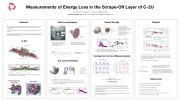
Abstract
▪ An end loss analyzer system (ELA) was developed to study thermal transport on the open field lines that surround the advanced beam-driven field-reversed configuration (FRC) core of the C-2U experiment [1,2,3].
▪ The ELA consists of electrostatic, gridded retarding potential analyzers and pyroelectric crystal bolometers.
▪ The system measures the ion current density as well as the total power flux to enable calculation of the energy lost per escaping electron / ion pair. This ratio is a key metric for understanding electron heat transport on open field lines [4,5].
End Loss Analyzer
GEA
Plasma Gun Location
Bolometer
Power Density
Results
Some of the power lost from the core went “missing” at low plasma gun bias voltage Plotted quantities are time-averaged over the main part of each shot (0.5-1.5 ms).
For low plasma gun bias voltage, the bolometers measure less power than is implied by the level of power loss from the core.
Ion current always agrees with core particle loss
C-2U
Neutral Beams
▪ Two electrostatic ion energy analyzers and two pyroelectric bolometers mounted in the south divertor, directly on the divertor electrode.
Measurements of Energy Loss in the Scrape-Off Layer of C-2U
Bolometer
GEA
M. E. Griswold, S. Korepanov, M. C. Thompson, and the TAE Team
TRI ALPHA ENERGY, INC., P.O. Box 7010, Rancho Santa Margarita, CA 92688-7010
End Loss Analyzer
Divertor electrodes
Plasma Gun
▪ Located just outside a plasma gun that is used in conjunction with the electrodes to control the radial electric field in the plasma
▪ Vacuum magnetic field for a representative shot
I
p
= γ cρδ
× Q
▪ LiTa03 pyroelectric crystal measures incident power.
▪ A permanent polarization varies with temperature, causing current to flow in an external circuit.
▪ Springs isolate the crystal from mechanical vibration caused by pulse magnets to reduce piezoelectric noise
ion curr. density (kA/m2)
power density (MW/m2)
Expander
FRC core
Power Density
t (ms)
▪ Current and power densities at the divertor electrodes are calculated from power and current outflows from the core using two free parameters. The effective area of the electrode, Aeff=1 m2,
slightly less than the real electrode area of 1.2 m2 and the fraction of fast ions that are lost before they reach the divertor, FPL=0.7.
▪ The true radial profile of current and power at the divertor is unknown because the ELA only measures at one location.
▪ Both parameters are chosen to fit the data. However, holding the parameters fixed across multiple shots yields reasonable agreement
Eie /Te =65 Ei =qQ=2.6keV
Ji
▪ Te = 40 eV taken from helium jet imaging diagnostic measurements on the scrape-off layer [7].
▪ For an isolated and collision less mirror, Eie/Te ~8
▪ These measurements serve as a baseline for future
improvements on open-field-line electron confinement
▪ Results were taken during a limited operating period when the machine was in an unusual configuration (LaB6 biasing
in north divertor)
References
Divertor
Formation
Confinement Vessel
Mirror Plug
Mirror Plug
BA=.01 T
analyzer location
▪ Bolometer signal picks up noise from the plasma gun.
▪ The power measured by each bolometer can differ by a factor of 2. Bolometers measure
exactly the same power when the plasma gun doesn’t operate.
Comparison to Core Measurements
▪ Magnetic field surface contour lines and plasma density (color) in C-2U calculated by a 2-D magnetohydrodynamic numerical simulation[6]
Electrode Plates and Plasma Gum
LaB Cathode 6
0.5 x Aeff x [ (1-FPL) x Absorbed NB power – d/dt (core thermal inventory) ] Ion Current Density from Core Loss
0.5 x Aeff x [-d/dt (core particle inventory) ]
BM=1.3 T
▪ ▪ ▪
▪
Ion Current Density
▪ Ion current density measured by four grid analyzer
▪ Electrodes #1-3 held at electrode potential (Ve). Electrode #1 attenuates plasma, #2 and 3
are only used for ion energy measurement, and #4 repels primary electrons and suppresses secondary electrons from the collector.
Ion Current Density
t (ms)
Power Density from Core Loss
[1] M.W. Binderbauer et al., Phys. Plasmas 22, 056110 (2015) [2] M. Tuszewski et. al, Phys. Rev. Lett 108, 255008 (2012) [3] H.Y. Guo et al., Nature Comm 6, 6897 (2015)
[4] L.C. Steinhauer, Phys. Fluids B 4, 4012 (1992)
[5] D.D. Ryutov et al., Fusion Sci. Technol. 47, 148 (2005)
[6] L. Galeotti, D.C. Barnes, F. Ceccherini, and F. Pegoraro, Phys. Plasmas 18 (2011). [7] D. Osin and T. Schindler, Rev. Sci. Instrum. 87 (2016)
| 1 |
