
Page 1 - Measurements of Energy Loss in the Scrape-Off Layer of C-2U
P. 1
1.0
0.8
0.6
0.4
0.2
pulsed magnets
5 Filtered Dα imaging reveals warm neutrals
0.0
jet plasma
plasma gun
even inside separatrix
shot: 45844
t: -0.709 ms exposure: 1247.0 μs
50
50
Model View Sensor Typ. Frame
intrinsic camera parameters: • focal lengths: (fx, fy)
skew: γ
• center pixel offset: (cx, cy)
measured b = P · ε (emissivity) 1.0 0.6
0.4 0.2 0.0
• •
nO4+
/ne shot:45967
[1] [2]
M.W. Binderbauer et al. Physics of Plasmas 22 (2015), p. 056110.
J. Kannala and S.S. Brandt. IEEE Transactions on Pattern Analysis and Machine In- telligence 28.8 (Aug. 2006), pp. 1335–1340.
A. H. Andersen and A. C. Kak. en. Ultrasonic Imaging 6.1 (Jan. 1984), pp. 81–94. W.H. Meyer, M.E. Fenstermacher, and M. Groth. 56TH Annual Meeting of the APS Division of Plasma Physics. Vol. 59. Bulletin of the American Physical Society 15. 2014.
Daren Stotler and Charles Karney. en. Contributions to Plasma Physics 34.2-3 (1994), pp. 392–397.
M. Onofri, CP10.00088 this session.
150
100
50
0
50
100
100
50
0
50
→
1.5
bleed sources not known
100
50
0
50
100
1.0
0.5
0.0 Z [m]
0.5
1.0
100
50
0 px
50
100
0.8
S divertor
equilibrium vessel
biased electrode
N formation
N divertor
using imaging and Degas2
npx × nsources matrix A
• Shot 45306 Radial Camera Best Fit, t: 1.5 ms
DC magnets
5
0
Cylindrical axis (meters)
FRC
5
NB4
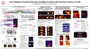
Fast imaging measurements and modeling of neutral and impurity density on C-2U
E.M. Granstedt, B. Deng, D.K. Gupta, D. Osin, T. Roche, K. Zhai, the TAE Team
Tri Alpha Energy, Inc., P.O. Box 7010 Rancho Santa Margarita, CA 92688
baxial
px
[m]
R Paxial
Pradial
px
bradial
t: 3.48 ms, Z [m]
t: 2.46 ms, Z [m]
t: 1.44 ms, Z [m]
datum index
datum index
Z+
nO /nO (equ. ionization balance)
core Te range
H-alpha radiance [W/m2/sr] H-alpha radiance [W/m2/sr]
H-alpha radiance [W/m2/sr] H-alpha radiance [W/m2/sr]
H-alpha radiance [W/m2/sr] H-alpha radiance [W/m2/sr]
H-alpha radiance [W/m2/sr] H-alpha radiance [W/m2/sr]
t: 4.50 ms, Z [m]
t: 3.48 ms, Z [m]
t: 2.46 ms, Z [m]
t: 1.44 ms, Z [m]
R [cm]
Mean Effective H density Z<Ztp [m−3]
px
Effective H density [m−3]
Error [W/m2-sr]
W/m3
W/m3
W/m3
W/m3
t: 5.817 ms [5.768,5.866 ms]
t: 5.794 ms [5.595,5.992 ms]
Transmission or QE
NUC: Relative illumination
MTF [%]
O1+ 3p→3s
Ar1 + 4p(2 F) →4s
C2+ 3p→3s
Ar1 + 4p(2 D) →4s
O5+ 8→7
O4+ 4p→4s H/D-α
He0+ 3d→2p
He0 + Ar0 + He0 +
3s(3 S) →2p 4p(2 F) →4s 3s(1 S) →2p
Wide-angle radial view
Nearly axial view
Radius (meters)
t: 0.988 ms [0.939,1.037 ms]
t: 0.993 ms [0.795,1.192 ms]
t: 3.822 ms [3.773,3.871 ms]
t: 3.793 ms [3.595,3.992 ms]
t: 6.971 ms [6.922,7.020 ms]
t: 6.993 ms [6.795,7.192 ms]
Radial camera
Axial camera
Brightness [W/m2-sr] px
Instrument Design
Nearly orthogonal views through equilibrium vessel
Optics design, calibration
Optical system optimized for for narrow-band filters, light throughput
r∆Φ
m Z:
NB2 NB1
shot: 46326
t: 2.009 ms exposure: 247.0 μs
NB5
NB3 NB4
NB1
NB2 NB1
shot: 46326
t: 3.259 ms exposure: 247.0 μs
NB5
NB3 NB4
NB5
NB2
NB3
NB1
+Y +X
axial camera
side view
top view
50
0 50 px
50
0 px
50
S formation
t: 1.0ms t: 3.8ms t: 5.8ms t: 7.0ms
• • •
•
6NBsat15keV,10MWtotal ∼ 700 A H source
beam capture via CX with thermal plasma
NBs into gas
shot: 45844 NB6 t: -0.379 ms
Fit
Error
Camera Specifications •
1.5
1.0
0.5
0.0 Z [m]
0.5
1.0
1.5
13.5 13.5 12.0 12.0 10.5 10.5 9.0 9.0 7.5 7.5
Vision Research Phantom v5.2
Axial 10.3x13.2 mm, 12 bit 256x256 @ 15564 fps
Sanstreak Edgertronic
Radial 17.92x14.34 mm, 10 bit 192x192 @ 9526 fps
generic camera model
Simulated forward projection
10 10-1
10 10-3 10-4
50 50
0.45 0.30 0.15
0.45 0.30 0.15
50 50
100 100 50
px
0.6 0.4 0.2 0.0 0.2
←0.4 0.6 150 1.5
100 100
22
-2
recyling and
2 (r −rpk)
, ψ(r,z) = Hill(r,z;rpk,l), e(r,z) = e(ψ)
e(r) = sech
(rpk, α, l) = (0.20 m, 0.21 m 1.00 m)
α
2
C-2U1 machine layout
Oxygen emissivity tomographic reconstruction
Neutral density estimated
Source weights optimized to best match experimental images
• simulated images cast as • unknown magnitudes m
•
3.2
2.8 100 2.4
2.0
1.6 0 1.2
0.8
0.4
100
Warm
over recycled neutrals
100
6 3 0 3 60 Residual [px]
mean: 0.334 σ: 0.636
T [eV] e
1.5
1.0
0.5
0.0 Z [m]
0.5
1.0
1.5
imaging • 40–60 cm viewport to camera lens
NB4
•
•
CAD geometry mapped to im- age space using camera model model parameters optimized to match port outlines in image pixel sightlines integrated to
01234567 r-residual [px]
0
•
Residual [px] mean: 1.078
100
100 50
100 50
0.032 0.032
0.028 0.028
0.024 0.024 [4] 0.020 0.020
0.016 0.016
0.012 0.012 [5] 0.008 0.008
0.004 0.004 [6]
In-situ spatial calibration using vessel
NBI
NBI
NB dumNpB, dRudmump,pR: d1u.0mp: 1.0
2.7 2.7
2 extrinsic parameters:
100
100 50
2.4 2.4 2.1 2.1 1.8 1.8 1.5 1.5 1.2 1.2 0.9 0.9 0.6 0.6 0.3 0.3
•
• • orientation: pitch, yaw, roll
Axial Camera Coordinate Mapping, method: ext+int+2rad
O4+ impurity concentration estimated using collisional-radiative modeling
50
aperture position x polynomial radial function
20000
15000
•
• • 2-5 params
0
6.0 6.0 4.5 4.5 3.0 3.0 1.5 1.5
•
• form projection matrix P
50
050
50 50
050
50
50
skew
0.7
0.6
0.5Radial Camera Coordinate Mapping, method: ext+int+σ2:r1a.1d90
[3]
0.4
0.3 datums
0.2
0.1 mapping
0.0 25000
20000
15000
10000
5000
50
01234567 r-residual [px]
x y r
amplifies noise and regions with low signal equ. ionization balance: ⇒ Z = 6+ dominant
Z:0 Z:2 Z:4 Z:6 Z:8 Z:1 Z:3 Z:5 Z:7
0.5 0.4 0.3 0.2 0.1 0.0 0.5 0.4 0.3 0.2 0.1 0.0 0.5 0.4 0.3 0.2 0.1 0.0
r∆Φ
5.4e-05 4.8e-05 4.2e-05 3.6e-05 3e-05 2.4e-05 1.8e-05 1.2e-05 60e-06
4.8e-05 4.2e-05 3.6e-05 3e-05 2.4e-05 1.8e-05 1.2e-05 6e-06
0
0.00012 0.000105 9e-05 7.5e-05 6e-05 4.5e-05 3e-05 1.5e-05 0
NB gasNbBlegeads, b2l.e0etdo,rr2-.L0/storr-L/s
image b is a superposition
of each source magnitudes of
Wall reWcyacllinregc:y6c.l0inAgH: 6t.o0tAalH total
0.036 0.036
datums mapping
10000
5000
200
100
0
Z [cm]
100
200
0 84048
0.90 0.75 0.60
0.90 0.75 0.60
x
y
r 10
-5 100
101
102
103
O
4+
(650 nm 3d → 3p) brightness gradient near magnetic RΔΦ
non-negative least-squares measured image b solution: A · m = b
1.03 0.72
0.24
-0.24
-0.72 -1.03
-1.74 -2.67
1.03 0.72
0.24
-0.24
-0.72 -1.03
-1.74 -2.67
1.03 0.72
0.24
-0.24
-0.72 -1.03
-1.74 -2.67
1.03 0.72
0.24
-0.24
-0.72 -1.03
-1.74 -2.67
NB2 “warm” neutrals generated NB1
NB6 NB5
NB2 NB1
NB3
100
50
0
50
100
DCA02 (adj) shot:45838
DCA02 (adj) shot:45838 DCA02 (adj) shot:45838 DCA02 (adj) shot:45838
exposure: 979.4 μs
0.60 0.45 0.30 0.15 0.00
0.15 0.30 0.45 0.60
Z: Z: Z: Z:
NB5
NB3 NB4
r∆Φ mmmm
r∆Φ r∆Φ
m
Full shot, NBs on
shot: 46326
t: 2.049 ms exposure: 98.0 μs
NB5 NB2
NB4 NB3
Full shot, NBs off
shot: 46326
t: 3.308 ms exposure: 98.0 μs
DCA07A (raw) shot:45838
0.24 -0.24
DCA07A (raw) shot:45838
0.24 -0.24
r∆Φ r∆Φ
DCA07A (raw) shot:45838
0.24 -0.24
r∆Φ r∆Φ
DCA07A (raw) shot:45838
input group secondary group
output group
+Z
35◦ FOV
• <73.0 mm dia optics envelope • >1.0 nm filter bandwidth
Detector line pairs/px
Algebraic Reconstruction Technique3,4
• • • •
• •
• •
• •
• •
Neutral sources modeled with Degas2
strongly non-axissymmetric Hα /Dα emission 2-D tomographic reconstruction not possible ⇒ use Degas2 as interpretive tool
neutrals
dominate
+Y
+Z •
Photometric calibration
flux function
simulation6
assume plasma quanti- ties are flux functions ⇒ extend profiles axially to 2D
experimental values for NB particle currents, en- ergy fractions
also sources from NB
10
10
10
10
17
16
15
14 0.0
100 50 0 50 100
imaging+Degas2: all neutrals
1D array+NB term: plasma recycling gas bleed
•
•
+X
r
∆Φ
0.16 0.14 0.12 0.10 0.08 0.06 0.04 0.02 0.00
0.16 0.14 0.12 0.10 0.08 0.06 0.04 0.02 0.00
0.28 0.24 0.20 0.16 0.12 0.08 0.04 0.00
0.72 0.64 0.56 0.48 0.40 0.32 0.24 0.16 0.08 0.00
1, ⇒ over-predicts warm neutral source
simulation treats thermal
absolute calibration error?
121◦ FOV radial camera
mapped nonlinear detector re- sponse
absolute photon efficiency measured for each filter
QE and transmission
residual errors typically ∼10%
simulation assumes Z =
Retractable design for gettering protection
0.1
0.2
0.3 0.4 R [m]
0.5
0.6
0.7
•
• plasma as H not D
• removable for
• cleaning
• sapphire viewport
protective cap around mirror
sapphire window
10x 2" dia filter wheel
support electronics
camera black anodizedwith lens
enclosure
mirror adjustment screw
end-cap
304SS mirror
re-entrant tube
motorized bellows actuator
1.0
0.8 (theoretical
1.0 0.1 (64 px, 0.97)
Neutral density distribution
cut along a single azimuthal plane
• •
lens-based optical periscope optimized for F/2.0
Gaussian smoothing applied to b image
•
0.6 0.5 0.4 0.3 0.2 0.1 0.0 0.5 0.4 0.3 0.2
ART emissivity shot:45967
eff
0.6 0.4 0.2 0.0
350
(192 px, 0.52)
400
450
500
650
700
750
50
100
Radial distance [px]
Synthetic cameras enable comparison between simulation and experiment
10 10 1015 1014
relay optics transmission)
0.8 0.6 0.4 0.2
800 0.0 0
(96 px, 0.95) (128 px, 0.91)
200 250
0.0 0.5 0.4 0.3 0.2 0.1 0.0 0.5 0.4 0.3 0.2 0.1 0.0
dump, gas recycling
bleed,
wall
Edgertronic QE
Phantom v5.2 QE
550 600 Wavelength [nm]
17
100 0.10
80 60 40 20
0.15 0.20
0.25 0.30
0.35
•
• Recall back-projection: ε
0
0.02 0.03 0.04 0.05 0.06 0.07 0.08 0.09 0.10 0.11
Target line pairs/mm
ε =ε +λ P ·FHP b−P·ε • tunable parameters:
midplane
Mean effective neutral density
sion ≲ 13 W/m -sr and mea- surement ≲ 3 W/m2-sr beam emission in Degas2,
Relative response
Optics nonuniformity
from Q2D
but outside
filter bandwidth
experimental
150
Z:
m Z:
m Z:
0.24 -0.24
= PT · b
SART iterates back-projected error to convergence:
• Degas2 warm-neutral emis- 2
• [ ( )] k+1kT k
• λ: speed vs. stability
•• FHP(x): high-pass filter shape, cut-off frequency
experimental
plasma profiles
fast ion density, magnetic
Plasma profiles
4+ nO
ne
ε nePEC3d→3p (ne, Te)
50 50
50 100
50
100
50 050 50 50
=
3d→3p 0.6
grated along
BP
2
r each pixel
References
58th Annual Meeting of the APS Division of Plasma Physics
San Jose, California
used physical
camera spatial
calibration emission inte-
100
50 050 50 50
sight-cone f experimental
o
1
00
100 100 50 50 00 00
100 50 00 00
16
| 1 |
