
Page 1 - iallfrey_aps-dpp2016_poster_draft_05_hg_fixed.pptx
P. 1
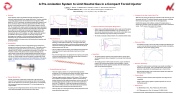
■  Abstract:
Fusion plasmas require long lifetimes and high temperatures, both of
which are limited by particle loss, among other factors. Therefore, refueling a long-lived advanced beam-driven field-reversed configuration (FRC) plasma in C-2U [1] is necessary, and injecting a supersonic compact toroid (CT) is an effective means of introducing particles into the FRC core [2]. However, neutral gas that trails the CT into the target chamber cools the FRC. Pre-ionization (PI) system assists the break down between electrodes of the CT injector (CTI), so the amount of introduced gas can be lowered by up to a factor of two, effectively increasing the ionization fraction; thus, reducing the amount of neutral gas in the system. Additionally, the PI decreases the delay in CTI breakdown so a highly reproducible operation is achievable. The PI system consists of a fast, high voltage, pulse discharge circuit coupled to a Teflon insulated semi-rigid coaxial cable inserted into the CTI. System details and experimental data will be presented, in addition to issues such as the introduction of impurities and pre-ionizer lifetime.
■  Introduction:
A drawback of injecting a CTI into a target plasma is the cooling of the
plasma by the excess neutral gas that follows the CT. Furthermore, with a high frequency multi-pulse CTI the excess neutral from the first pulse remains in the CTI, which is accumulated as successive CTs are fired. The PI system consists of the plasma source and pulse discharge circuit, which injects a small amount of plasma between the electrodes of the CT injector. This plasma reduces the required amount of neutral gas puffed into the CTI. These benefits come at the expense of introducing a small amount of impurities into the plasma and the limited lifetime of the plasma source. See details of CT and FRC interaction in T. Matsumoto’s poster (CP10.00083).
■  Excess Neutral Gas:
Density, measured by a dispersion interferometer, indicates that the
second CT has a density almost twice as high as the first on the leading edge. The fact that the CT is “front heavy” shows the CT is accumulating the excess neutral gas from the previous CT, as it accelerates into the target chamber.
According to time of flight measurements the second CT takes longer to reach the photomultiplier tube array and has a lower speed.
2.5 2.0 1.5 1.0 0.5 0.0
0
Density, Shot 4363
100
Time(μs)
First CT
Pulse 1
Pulse 2
150 200
PMT TOF, Shot 4363, First CT
1.0 PMT 1, -20cm 0.8 PMT 2, -71cm
0.6 0.4 0.2 0.0
PMT TOF, Shot 4363, Second CT
1.0 PMT 1, -20cm 0.8 PMT 2, -71cm
■  Changes in the Gas Load of the CTIs:
With the PI, the amount of injected gas required to break down the gun has
decreased, while the CT’s particle inventory remains the same, indicating there is less neutral gas to trail the CT into the target plasma.
Dα (656.3nm) signal, which indicates cooling of the target plasma, is
measured on the North C plane (CT injection plane) of C-2U’s confinement
vessel. The PI causes a decrease in the Dα signal.
A Pre-ionization System to Limit Neutral Gas in a Compact Toroid Injector
■  Plasma Source:
0.8 0.6 0.4 0.2 0.0
 0.2
 0.4
 0.6
0 20
0.00 1 2 3 4 5 Time(ms)
■  Delay and Jitter:
■
■
■
The plasma source is a simple design which relies on the surface discharge of Teflon(C2F4) insulated 1/4” semi-rigid coaxial cable, inserted into vacuum by way of a conflat mounted compression fitting. The plasma created by the breakdown is accelerated into the gun by plasma pressure and JxB force.
There is indication that the plasma source lifetime may be limited to a few hundred shots, though comprehensive tests have not been performed.
Also, the semi-rigid coax is not appropriate for a high vacuum system, as there are leaks between the electrodes and the Teflon insulator, in addition to the introduction of impurities.
■
The addition of the PI to the CTI decreases the delay of breakdown from
>1 μs to a few hundred nanoseconds and lowers the jitter considerably,
50
0 20 40 60 80 100 120
Time(μs)
Second CT
I. Allfrey, T. Roche, T. Matsumoto, E. Garate, H. Gota, T. Asai and the TAE Team
TRI ALPHA ENERGY, INC., P.O. Box 7010, Rancho Santa Margarita, CA 92688-7010 Nihon University, 1-8-14, Chiyoda-ku, Tokyo 101-8308, Japan
Intensity(a. u.)
Intensity(a. u.)
Current(kA)
D alpha(a. u.)
Intensity(a. u.)
Density(1015 /cm3 )
Light Intensity (a.u.) Light Intensity (a.u.)
■  Pulsed Discharge Circuit:
■  The power supply consists of a 3 μF pulse discharge capacitor, charged up to 10 kV, switched to ground by an ignitron, which outputs a negative pulse. The circuit has up to 150 J of stored energy.
■  The power supply needs to charge to ≥6 kV, where >7.5 kV allows for more reliable and consistant operation. Evidence, from bench top testing, indicates that the required capacitance can be as low as 40 nF and still produce plasma, though it is not clear if this is sufficient to assist the CTI breakdown. Lowering the energy should reduce the ablation of the Teflon and erosion of the electrodes may be lowered. This may also help to extend the life of the plasma source.
■  The PI has been run in multi-pulse mode by driving the plasma source by paralleled discharge circuits.
1.0 0.8 0.6 0.4 0.2 0.0
400 1.0
0.8 0.6 0.4 0.2 0.0
500
PI Emission Spectrum
600 700
Wavelength(nm)
800
0.6 0.4 0.2 0.0
■  Plasma Parameters with Optical Diagnostics:
■  Signals from an unfiltered photodiode, with an axial view of the plasma
source, indicate that the plasma lifetime, in air, is around 75 μs. In other words, the plasma lives about 15 μs after the current falls to zero, which is sufficiently long to help the main gun break down.
■  The electrical and optical measurements are consistent between shots. Photodiode, Axial View Compared with Current
■  Impurities:
40 60 80
Time(μs)
150
100
50
0
With PI
Without PI
25
■  The plasma emission spectrum was measured with an Ocean Optics survey spectrometer, whose integration time is longer than the plasma lifetime.
■  The leading species in the PI plasma are carbon, copper and flourine based on the most prominent peaks of the line radiation. The two largest peaks are due to copper and carbon, where the following five lines can be explained by fluorine.
10 15
505
510
515
520
525
530
535
PI Emission Spectrum
Wavelength(nm)
Presented at the 58th Annual Meeting of the APS Division of Plasma Physics
Current, Shot 1
Photodiode, Shot 1
Current, Shot 2
Photodiode, Shot 2
100 120
allowing for more precise control of timing.
1.0 D alpha Emission on NC Plane 0.8
0.6 0.4 0.2
Without PI
With PI
Delay Comparison
20
Time(μs)
■  Using a PI to reduce excess neutral gas is successful, according to a decrease in the Dα signal. This is possible because the PI system allows for a reduction in the injected gas by up to a factor of two.
■  Both the delay and jitter of the CTI has been reduced, which improves timing accuracy of injection.
■  Future Work:
■  Develop a PI which introduces fewer impurities and is high vacuum
compatible.
■  Design a power supply capable of repetitive operation for use on a multi-pulse system.
■  References:
■  [1] M. Binderbauer et al., Phys. Plasmas 22, 056110 (2015).
■  [2] T. Matsumoto et al., Rev. Sci. Instrum. 87, 053512 (2016)
■  Results / Summary:
| 1 |
