
An Interesting Poster to look at from the Tri Alpha Energy Team in California
P. 1
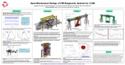
Opto-Mechanical Design of FIR Diagnostic System for C-2W
M. Beall, B.H. Deng, G. Settles, M. Rouillard, J. Schroeder, H. Gota, M. Thompson, G. Snitchler, S. Ziaei and the TAE Team TRI ALPHA ENERGY, INC., P.O. Box 7010, Rancho Santa Margarita, CA 92688-7010
Motivations
Upgraded interferometer/polarimeter on center plane of machine to provide high resolution density and magnetic field information
Original system on C-2 had 6 chords of CO2 below plasma center; system on C-2U added 4 chords of 432.8 μm Far Infrared (FIR) above center
Interferometer phase:
I (1No)k0dl
2.811015 n dl
CO2 can be improved 3x with reference chord subtraction, but FIR has 100 times better resolution than the two-color CO2/HeNe interferometer
Limited sampling by CO2 did not fully constrain plasma profile when plasma center was not on axis
FIR addition allowed for more complete mapping and reduction of error bars, but was widely spaced and not available for interferometry and polarimetry simultaneously
C-2W will have 14 chords of FIR with 8 cm spacing
Polarimeter phase:
ψ𝐹 = 2.62 × 10⁻¹³λ2 𝑛𝑒𝐵∥𝑑𝑙
Polarimetry on C-2U was very challenging due to low levels of expected Faraday rotation
0.1o sensitivity was achieved, but theoretical rotation is only 0.2o, allowing verification of field reversal but making sophisticated analysis challenging
In order to improve system sensitivity, the new C-2W FIR system was designed to minimize mechanical vibration
Vibrational phase error:
v 2 l
e
Constraints
FIR system in situ
As on most experimental devices, space is at a premium and the large FIR system is at the most desirable location, on the midplane of the device
As such, certain allowances are required to provide the diagnostic structure with necessary structural elements without conflicting with critical machine components
Magnets, vessel supports, deck supports and large neutral beam chambers prevent the use of any large support structure near the vessel, and accessibility requirements restrict the use of monolithic columns
Available port locations and desired impact parameters require suspension of an optical breadboard above the machine, rigidly tied to a corresponding board on the underside
Proximity of the optical breadboards to the vessel magnets resulted in ~100N kick on metallic breadboards due to eddy currents during ramp up, according to initial analysis
Resultant deflection exceeds required value of 0.2 μm
For this reason, optical boards adjacent to magnets have been replaced with
canvas phenolic
Design
FIR structure
C-2W will have 14 chords of 432.8 μm FIR at the midplane, spaced every 8 cm from -52 to +52 cm (vessel ID 160cm)
Extent comparable to outermost chord in C-2U, with chord density comparable to CO2 chords (twice as dense as FIR)
Beams generated by 3 HCOOH (formic acid) lasers, pumped by 2 CO2 lasers
Simultaneously operating in both interferometry and polarimetry modes
7 of 14 chords tilted at 15o angle off perpendicular to assist polarimetry
Breadboards made of canvas phenolic, reducing predicted magnetic force by
factor of 100
Primary rigid mechanical support placed further away from the vessel to hold load
and resist impulse forces on the system
“Soft” secondary support of lower breadboard to reduce sway of pendulum mode
System Schematic
Beam waist design
Total mass ~30000lb
Long wavelength requires special attention to manage beam size over long path length
Due to spatial constraints, waveguiding is impractical
Longest optical path ~16 m, beam profile designed to keep 99.9% beam power
below 4.5” diameter
Vessel window clearance 2.75”, beam size maintained with 0.5” tolerance for ease
of alignment
Analysis
System vibration modeled in Ansys to confirm expected performance would match tolerances
Figure of merit for analysis was path length change over the beam trajectory, corresponding to vibration induced phase change in the detector
Input excitation sources from both designed magnet behavior and on-site measurements of ground vibrations, acoustics and transient events
Conservative results indicate that high frequency response and short time interval behavior of the structure should meet desired specifications
Additional vibrational damping prospects to be tested and analyzed
Abstract
The goal of the C-2W far-infrared (FIR) diagnostic system is to provide highly accurate, simultaneous polarimetry and interferometry information about the generation, equilibrium and time evolution of the advanced beam-driven field-reversed configuration (FRC). Thorough spatial coverage of the confinement vessel will be provided by a set of 14 chords at the central plane, with half of the chords tilted at a 15° angle to provide additional polarimetry information. Due to the very low (< .5°) Faraday rotation expected in the field-reversed plasma, the system has a design goal of .25 μm maximum allowable vibration over the lifetime of the shot. Due to large eddy-current forces from simulation of magnetic-field ramp-up, a non-metallic canvas phenolic material has been selected for the primary breadboards, which are mounted on a rigid, sand-filled support structure. Given the size of the structure and the magnetic impact, the support structure does not use pneumatic or mechanical isolation. Dynamic vibration analysis with Ansys, based on measurements of local ground vibration and simulations of magnetic forces, predicts that the system will meet the design goal.
58th Annual Meeting of the APS Division of Plasma Physics, San Jose, California, October 31 – November 4, 2015
| 1 |
