
Neutral Beam Injection System for the C-2W Field Reversed Configuration Experiment
P. 1
Abstract
A magnetized coaxial plasmoid accelerator has been utilized for compact torus (CT) injection to refuel into fusion reactor core plasma. Recently, CT injection experiments have been conducted on the C-2/C-2U facility at Tri Alpha Energy [1,2]. In the series of experiments successful refueling, i.e. increased particle inventory of field-reversed configuration (FRC) plasma without disruption, has been observed. In order to improve the performance of CT injector and to refuel into the upgraded FRC device, called C-2W, with higher confinement magnetic field, magnetic circuit consisting of magnetic material onto a bias magnetic coil is currently being tested at Nihon University. Numerical work suggests that the optimized bias magnetic field distribution realizes the increased injection velocity because of higher conversion efficiency of Lorenz self force to kinetic energy. Details of the magnetic circuit design as well as results of the test experiment and field calculations will be presented and discussed.
[1] T. Matsumoto et al., Rev. Sci. Instrum. 87, 053512 (2016). [2] T. Roche et al., Bull. Am. Phys. Soc. 60, BP12.00023 (2015).
Magnetized Coaxial Plasma Gun (MCPG)
Improved bias coil
Reference MCPG/CT parameters
n NEWbiascoilwillbecomparedwithparametersderivedfroma simpler bias coil, as shown in right figure
n ThefollowingfiguresshowthetypicalMCPG/CTparameters,for which the CT was formed using original bias coil
Inner electrode
Outer electrode
Gas inlet
NAME
Enameled wire
SS tube Acrylic pipe
Iron core
Time [μs]
Triple Langmuir probe
Fiber 2
Fiber 1
Inner magnetic probe array
Mach probe
MCPG
Plasma generated by new setup
n Newpowersupplyanddiagnosticshavebeenprepared n Asafirstdischarge,wetrieddischargeswithoutbiascoil n Theplasmawasejectedandemittedlightonthedrifttube
150
50
0
-50 [cm]
Ceramic break
Bias coil
Iron core
Diameter [mm]
φ1.0
O.D.φ34 O.D.φ45
Φ26
Length Thickness [mm] [mm]
531 - (Estimated length )
600 2.8 600 2.0
700 -
time [μs]
Schematic view of magnetized coaxial plasma gun
[μWb] 10
8 46
2 0
[mWb]
1.2 0.8 0.4 0
e Electron temperature Te
Diagnostic setup to evaluate an ejected CT
Outer electrode
Gas inlet
Drift tube
100
w/oIroncore
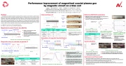
n Infigureabove,thecontoursshow magnetic flux distribution
n Theedgeofbiascoilislocatedaroundthe gasport
n In case w/ Iron core, radial magnetic field is more uniform. This is important effect because Br drives toroidal current of CT
n LeftfigureshowsthedistributionofBronz- axis between electrodes. Red line shows w/ iron core and blue line shows w/o Iron core
n BrwithIroncoreis30xstrongerthanw/o Iron core case, and also the Br is spread by Iron core along z-axis.
Schematic view of diagnostic setup to evaluate ejected CT parameters; this test stand is located in Nihon University
Diagnostic list
Rogowski coil Chain resistor
Triple Langmuir probe Inner magnetic probe array Mach probe Collimated fibers
Bias coil current Ibias: 5 A Relative permeability μ/μ0 : 4000
n Thedischargehasalreadysucceeded Conclusion and Future work
n WeproposedaNEWcontrolmethodforradialmagneticfieldbyIroncoreaspartofbiascoil.
n Accordingtoresultofsimulation,BrwithIroncoreis30xstrongerthanwithoutIroncorecase.Alsothe
distribution can be controlled by changing the location of the Iron core.
n Asacurrentsituation,wearereadyforexperimentwithNEWbiascoilw/Ironcore.
n Inthenearfuture,wewillcomparetheCTformedwithdifferentbiascoils(w/orw/oIroncore)andthen
verify effect of Iron core.
MCPG
Drift tube
Measuring objects
Gun current Gun voltage
Electron density and temperature Magnetic field profile Plasma flow
Travel velocity
n n
n
MCPG is constructed with coaxial cylindrical electrodes
Bias coil is inserted inside the inner electrode and consists of SS tube, Enameled wire, Acrylic pipe, and Iron core Ironcoreismovableanditspositioncanbe easily changed
Guncurrentatpeak
Rise time
Current situation
100 Charging voltage : 20 kV 80 Capacitance : 4.8 μF
60 Peaked gun current : 88 kA 40 Rise time : 3.5 μs
20 0 -20 -40 -60
-5 0 5 10 15 20 25 30 35
tTimime [eus][μs]
Time evolution of gun current
n Weusefastbankstoapplyhigh voltageandfasterrisetime
Time evolution of (a) electron density and (b) temperature
n Measured by Triple Langmuir probe
n Thedottedlinesrepresent average value
n Ejected CT maintains high density and high temperature
Probe position [mm]
Distribution of magnetic field inside the ejected CT. (a) y direction, (b) z direction
n Measured by inner magnetic probe array at 160 μs after breakdown
n This distribution is similar with spheromak: (a) toroidal field, (b) poloidal field
After breakdown
Performance improvement of magnetized coaxial plasma gun by magnetic circuit on a bias coil
T. EDO,1 T. MATSUMOTO,1 T. ASAI,1 Y. KAMINO,2 M. INOMOTO,2 H. GOTA3 1College of Science and Technology, Nihon University, Chiyoda-ku, Tokyo 101-8308, Japan
2Graduate school Frontier Sciences, the University of Tokyo, Bunkyo-ku, Tokyo 113-8654, Japan 3TRI ALPHA ENERGY, INC., P.O. Box 7010, Rancho Santa Margarita, CA 92688-7010, USA
Acrylicpipe
Iron core
Enameled wire wound onto SS tube (1000 turns)
Bias coil installed into Acrylic pipe
Iron core inserted into bias coil
Production process of bias coil
n Acrylic pipe installed to isolate from others
n DC current is applied to bias coil for poloidalmagneticfieldofCT
Enameled wire
80 60 40 20
0 -20 -40 -60
Charging voltage : 10 kV Capacitance : 160 μF
1.0
0.8 (a)
0.6 0.4 0.2
100
0.0 (b)
80 60 40 20
0 180
Original bias coil (58 turns)
30
20 (a)
Configuration of bias coil
-50 0 50 100 150 200 250 300 350 400
-6
SS tube
SStube
Enameled wire
Acrylic pipe
Iron core
Others
1000 turns (500 turns, 2 layers)
- -
-
Enameled wire
10 0
-10 -20
20 10 0 -10 -20 -30 -40
-100 -50 0
(b)
50 100
Simulation of magnetic flux distribution
Electron density <n >
80kA
24 μs
2.0 × 10²⁰ m-3 50 eV
25 20 15 10 5 0 -5 -10[cm] 25 20 15 10 5 0 -5 -10[cm]
Inner electrode
w/o Iron core Iron core w/ Iron core Simulated magnetic flux profile from bias coil (w/o, w/ iron core)
w/ Iron core
Comparison of distribution of radial magnetic field
x10
Time [μs]
Time evolution of gun current
n The charging voltage was 10 kV, and the capacitance was 160 μF
MCPG parameters
190
200
210
220
Before breakdown
Br [mT]
gun current [kA]
Gun current [kA]
3
Gun cuxr1r0ent [kA]
T [eV] n [×1021/m3] T [eV] N [x1021/m3]
ee ee
Bz [mT] By [mT]
| 1 |
