
Page 4 - Gyrokinetic simulation of driftwave instability in field-reversed configuration
P. 4
056111-4 Fulton et al.
TABLE I. Equilibrium parameters used in both the core and SOL simulation
Phys. Plasmas 23, 056111 (2016)
regions.
Ti qi qe
400 eV
5.3 cm 0.039 cm
200 eV
2.3 cm 0.017 cm
Core
SOL
B0 533.7 G
ne 4:0 1013 cm 3
Te 80eV 40eV
quantities are presented in Table I, including the ion and pffiffiffiffiffiffiffiffi pffiffiffiffiffiffiffiffiffiffi
electron gyro-radii (qi 1⁄4 miTi=ðeBÞ; qe 1⁄4 meTe=ðeBÞ).
Transit frequencies and effective collisionalities are
listed in Table II. The transit frequency describes how often
a particle completes a circuit on a field line. For electrons
and ions on a field-line of length l, the respective transit fre-
quencies are defined tr;e 1⁄4 Vth;e=l and tr;i 1⁄4 Vth;i=l, respec-
tively, where Vth;a is the thermal velocity of a particle
species, a. Transit frequencies are normalized by the ratio of pffiffiffiffiffiffiffiffiffiffiffi
the major radius, R0 to the sound speed, Cs 1⁄4 Te =mi . In
the core, the field-line length is estimated by
l1⁄4ðR0 þrÞ p, and in the SOL, l 5m, which is the
length of the simulation domain. Effective collisionality is
the ratio of the collisional frequency to the transit frequency
and characterizes the relative importance of collisional
effects. When 1, collisions have only a small effect a1 a2
and become very important as 1. Here is the a1 a2 a1 a2
effective collisionality between species a1 and a2, and the
unstarred a1 a2 represents the unnormalized collisional fre-
quency. For electrons, e, and a single ion species, i,
1⁄4 e e= tr;e; 1⁄4 e i= tr;e, and 1⁄4 i i= tr;i. e e e i i i
Notably, the effective collisionality in an ideal FRC is quite low compared to a tokamak with the same major radius and temperature. Because the FRC has equilibrium magnetic field only in the poloidal direction, the field line length is short compared to a tokamak where field lines must make many toroidal circuits before closing. As a direct result, the transit frequency in the FRC is much higher, and, in turn, the effective collisionality is much lower.
In the core, ion-scale driftwave modes are found to be strongly stable using experimentally realistic values for den- sity and temperature gradients. Artificial increase of these gradients to the limits of gyrokinetic validity still yields no instability in the core. Magnetic field variation on the core- simulation flux surface is shown in Fig. 2. Modes with higher toroidal wavenumber, kfqi, well into electron-scale lengths,
TABLE II. Characteristic transit frequencies and effective collisionalities for each species in both the FRC core and SOL.
FIG. 2. Magnetic field structure, along the simulated flux surface in the FRC core. From top to bottom, field line curvature, magnetic field magnitude, and normalized magnetic field gradient are shown versus poloidal angle, h.
are easier to excite in the simulation, but these modes do not typically contribute significantly to transport. Careful inves- tigation of this high-wavenumber electron-scale driftwave turbulence will be reported in a future paper.
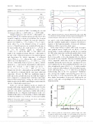
In the scrape-off layer, realistic values of the ion temper-
ature gradient inverse length scale are R0=LTi 2:5. As
shown in Fig. 3, modes with finite growth rate are found in
the SOL using temperature and density gradient drives in the
range R0=L 2 6. By varying the instability drive via
R0=L, it is possible to detect the minimal drive for which a
linear mode becomes unstable. This linear instability thresh-
old is comparable (with some caveats) to critical gradient
instability thresholds observed in the experiment. For ion-
scale length modes, the linear stability threshold occurs for a
drive strength in the range of R0=L 3 4, which is qualita-
tively consistent with nonlinear critical gradient measure-
ments, indicating R =L 5 6, taken in recent Doppler 0 crit
backscattering data on the C-2 experiment.13 Turbulence into electron-scale lengths, represented by green curves to the left in Fig. 3, is also present in the SOL. As expected, these higher wavenumber electron-scale length modes are easier to excite and, correspondingly, have lower linear sta- bility thresholds.
tr;e
tr;i
FIG. 3. Linear growth rate versus inverse gradient length scale (drive
strength) for simulated modes in FRC core (red) and SOL (green). The green
curves, from left to right, correspond to toroidal wavenumbers, kfq pffiffiffiffiffiffiffiffiffiffiffiffiffiffiffiffiffiffiffiffiffiffiffi s
16:43; 8:22; 4:11; 2:74; 1:37, where qs 1⁄4 mi ðTi þ Te Þ=ðeBÞ.
e e e i
i i
R0 Cs
R0 Cs
Core 5.47
1 2:02 10
1.16
2.45 1:20 10 1
SOL 3.23
1 1:24 10
3.81
8.61 2:61 10 1
2430.5 G 2:0 1013 cm 3
Reuse of AIP Publishing content is subject to the terms at: https://publishing.aip.org/authors/rights-and-permissions. Downloaded to IP: 128.200.44.221 On: Wed, 04 May 2016 16:35:05
