
An Interesting Poster to look at from the Tri Alpha Energy Team in California
P. 1
Abstract
CTI Test Stand
Fast-Framing Camera (nac image technology inc.)
[1] T. Matsumoto et al., Bull. Am. Phys. Soc. 59, UP8.00008 (2014). [2] M. Binderbauer et al., Phys. Plasmas 22, 056110 (2015).
Compact Toroid Injector (CTI) System
Transverse Magnetic Field Region
Compact Toroid Injection into FRC CT Injector arrangement on the C-2U confinement region
Multi-Pulse Circuit
Coax. cable
CT Injector
I.D. Φ83.1
Φ54 T e
Φ Bias Coil v⊥
Outer Electrode Copper Shell Etot Upeak
Schematic view of our designed Compact Toroid Injector
x
Copper Shell Effect
Ratio of skin depth
Particle Trajectory
Upper Bottom
t=0
r~r
s ΔΦ
200100 0 20 Bx (G)
Skin depth
(b)
δ: Skin depth
ρ: Resistivity of the
conductor
ω: Angular frequency of current
3.0 2.5 2.0 1.5 1.0 0.5
0 0
w/ Cu
w/o Cu
~100 km/s
30
z=51.1 time evolution of
μ: Magnetic permeability Equation of Magnetic Diffusion
σ: Dielectric Constant
μ: Magnetic permeability
Method: Alternative Direction Implicit (ADI)
Outer electrode
Inner electrode
Bias Coil
200
400 Vbias (V)
600
1st CT
2nd CT
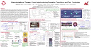
Characterization of Compact-Toroid Injection during Formation, Translation, and Field Penetration
T. Matsumoto,1 T. Roche,2 I. Allfrey, 2 J. Sekiguchi, 1 T. Asai, 1 H. Gota, 2 M. Corderoa, 2 E. Garate, 2 J. Kinley, 2 T. Valentine, 2 W. Waggoner, 2 M. Binderbauer, 2 T. Tajima, 2,3 and the TAE Team
We have developed a compact toroid (CT) injector system [1] for particle refueling of the advanced beam-driven
C-2U field-reversed configuration (FRC) plasma [2]. The CT injector is a magnetized coaxial plasma gun (MCPG),
and the produced CT must cross the perpendicular magnetic field surrounding the FRC for core refueling on C-2U. B-dot probe 10 To simulate this environment, an experimental test stand has been constructed. A transverse magnetic field of ~1
kG is established (comparable to the C-2U axial field) and CTs are fired across it. On the test stand we have been
characterizing/studying CT formation, ejection/translation from the MCPG, and penetration into transverse
magnetic fields. To vary CT formation parameters conductive copper shells are mounted around the outer B-dot probe electrode of the MCPG; the shells shape the bias field in a more effective and controlled way as well as improve
the initial high-voltage breakdown between the electrodes. The generated CT length is largely determined by the
relative position of the copper shells and the bias coil. In the transverse magnetic field region we can measure the
CT translation and field penetration event through a glass chamber. Installed diagnostics on the test stand are: Glass Tube internal/external B-dot probe arrays, arrays of collimated fibers, Langmuir probes, an interferometer, spectrometers,
and a fast framing camera. With this diagnostic suite on the test stand CT properties are well characterized and
optimized for C-2U CT injection experiments. The detailed test-stand experiments as well as recent results of CT 100 50
injection into C-2U FRCs will be presented and discussed at the meeting.
Transverse Field Coil
Schematic view of the CT Injector test stand, which is included MCPG, Drift tube, and Glass
t=33 μs
t=36 μs
t=39 μs
t=43 μs
CT/plasmoid shifted downwards
Camera Settings
Shutter Speed 600 kfps(2μs) Exposure time 1.5 μs
Specification (HS-106E) ISIS-CCD
Gas Injection Ports
Inner Electrode
O.D. n
Helmholtz-like coil
Current flow
~0.1T
Simulated Magnetic Field x-direction
Transverse filed coil
y
B-dot probe
17 cm
Collimated Fiber B-dot probe
Transverse coil Glass Tube
δss: Skin depth of Stainless Steel
δ : Skin depth of Cu
Copper
Copper shell
CT signal
time (μs)
st
1 port
1st port 3rd port
z=61.1 z = 71.1 cm
1
both magnetic probe arrays.
From this array, we can estimate the velocity of penetration inside the transverse magnetic field.
Bias Coil: movable Ceramic Break The Copper Shell: thin flat
To simulate the transverse magnetic field, a Helmholz-like magnetic field coil is constructed on the glass tube region.
This is a similar to the C-2U magnetic field surround the FRC.
CTI
1st
Distribution of magnetic flux from the bias coil
board
Thickness: ~1 mm
Magnetic Probe Array: Usually, the magnetic field is excluded by CT when the CT is penetrated to field. Then this probe array can measure this fluctuation and can assess trajectory and velocity.
Collimated Fiber Array: This fiber array can measure transverse displacement of the penetrated CT (e.g. vertical motion)
Injection axis
Quantity e
Value 5×10²¹ (m-3) 20-40 (eV) 0.4 (mWb) 100 (km/s) 0.4-0.8 (kJ) 50 (kJ/m3)
FRC
FRC
vion
(b)
-10 kV 2nd
Main Cap. Bank ~10 kV, 125 μF
Inner electrode
25
35
40 time (μs)
45
50
0 55 60-1
(a)
Outer electrode
(b)
Drift Tube
20
30
40
50
60
70
CT/plasmoid was injected into C-2U FRC
CT injections at t=0.5, 3.0 ms
Double CT injection has been succeeded
Line density increased about 10% at center chord
No disruption
Separatrix radius slightly decreased when the CT injected into FRC
injection port: (a) without
copper shell. (b) with copper shell.
Calculation results of single particle trajectory (black line) around gas
1Nihon University, Chiyoda-ku, Tokyo 101-8308, Japan
2TRI ALPHA ENERGY, INC., P.O. Box 7010, Rancho Santa Margarita, CA 92688-7010, USA 3Department of Physics and Astronomy, University of California, Irvine, Irvine, CA 92697, USA
Test Experiment Break down
Glass Tube
(a)
z=21.1 z=31.1 z=41.1
(a)
Left figure shows
vacuum field before
penetration of CT Right figure shows
Guiding Comparisonbetweenw/
(b)
Comparison Conclusion
Center
and w/o Cu shell.
Break down time with Cu shell is faster than w/o shell.
The copper shell is effective to break down.
CT is ejected around at 13 μs The magnetic probe installed to assess the CT timing
CT’s velocity estimated from fibers
between B-dot probe
and fiber array.
Markers are B-dot
probe signal at each time, contour plot is fibers signal
The CT was shifted downwards
As a NEW technique to control the break down, we developed the copper shell method
Our test stand can measure the typical physical parameters on the drift tube, such as velocity,
electron density, electron temperature
On the glass tube region, we measured velocity and trajectory of CT by magnetic probes and
fibers. These trace are comparable with fast camera frames/movie.
We succeeded to inject the CT into FRC and the FRC’s density was increased by CT injection
Fiber
B-dot probe
0
-150 cm
CT is located beneath
Fiber 1 tube
Triple probe
Dispersion Inter.
Drift Tube
-50 -100
Center Line
Fiber Array
Fiber 2
y
MCPG
Image Censor
Shutter Speed Frames Exposure time Pixels
image censor (Color)
60-1,250 kfps 120 100ns-open (H)360×(V)410
Diagnostics set-up on the glass tube
(a) Upper-view and (b) End-view of the C-2U Vessel Projection of the CT is near the machine center
Excluded-Flux Radius and Line-Integrated Electron Density
z
Diagnostic suits
MCPG: Rogowski coil,
Chain resistor
Drift Tube: B-dot
probe, Collimated fibers Interferometry, Triple Langmuir probe
Glass Tube: B-dot probe array, Collimated fiber array
trajectory
(a)
The multi-pulse uses a circuit similar to the single pulse power supply, but uses diodes as the crowbar and blocking element
Schematic diagram of Multi-Pulse Circuit
Bx (G)
Intensity (a.u.)
Intensity (a.u.)
Bz (G)
Current (kA)
break (μs)
ΔBx (G)
z (cm)
| 1 |
