
Page 2 - Internal magnetic field measurements of translated and merged field-reversed configuration plasmas in the FAT-CM device
P. 2
10J114-2
Gota et al.
Rev. Sci. Instrum. 89, 10J114 (2018)
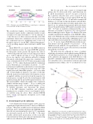
FIG.1. SchematicviewoftheFAT-CMdevice:centralregion—confinement vessel; both ends—R and V formation sections.
The overall device length is ∼8 m. Formation tubes are made of transparent quartz, and the confinement chamber is made of stainless steel (inner wall radius of ∼0.39 m; skin time of ∼5 ms) that serves as a flux conserver in the time scale of the experiments. Quasi-static confinement coils are placed along the confinement region for equilibrium field as well as in the mirror regions to ease the FRC collisional-merging pro- cess by providing adequate mirror field and a suitable axial profile.
Initial FRCs/CTs are formed by the FRTP method in the two formation sections. In a typical FAT-CM operation, the theta-pinch circuits generate the negative bias field of ∼0.038 T, followed by the main-reversal/compression field of up to ∼0.40 T with the rise time of ∼4 μs. The formation process also employs a pre-ionization method by a ringing theta-pinch-coil discharge. The quasi-static confinement coils create a forward field of 0.03–0.07 T with a strong mirror field of up to ∼0.2 T to confine the plasma inside the confinement region. Deuterium gas (total number of particles: ∼2 × 10²⁰ per formation) is puffed into each formation section using indi- vidual puff valves at around 4–6 ms prior to the start of the negative-bias field. Initial FRC plasmas, ∼0.07 m in radius and ∼1.0 m in length, are formed at ∼6 μs after t = 0 (the time when the main-reversal field in the both formation sections are applied), and they are ejected out from the respective for- mation regions at around 30 μs by the external magnetic field gradient generated by the tapered theta-pinch formation coils. The translated FRCs collide in the middle of the confinement chamber and then merge around t ∼ 50 μs, at which point the plasma radius reaches ∼0.2 m and the length is ∼1.5 m. To globally investigate and characterize the dynam- ics of the FRC formation, translation, and collisional- merging process, a number of in-/ex-vessel magnetic probes are installed along the device. More detailed FAT-CM device, system, and diagnostic descriptions can be found elsewhere.10,11
B. Internal magnetic probe radial array
A two-dimensional internal magnetic probe array was originally developed and used on the C-2 device at TAE Tech- nologies.7 This probe assembly was later transferred to Nihon University and is currently installed in the FAT-CM device. Since the two-axis internal probe array for C-2 experiments was previously reported (see Sec. II of Ref. 7), this paper describes only key probe specifications as well as some addi- tional information with regard to the new experimental setup and its in situ calibration on the FAT-CM device.
The two-axis probe array consists of 32 hand-wound pickup coils: 16 coils in each of the z and θ directions (for Bz and Bt measurements), spaced 3 cm apart, as shown in Fig. 2; therefore, the probe array covers a total of 45 cm in space. The probe housing is an end-capped SS304 tube that has an outer diameter (OD) of ∼4.2 mm with a nominal wall thickness of ∼0.05 mm. At this tube diameter and wall thick- ness, the L/R penetration time for both Bz and Bt fields is less than 0.1 μs. As a plasma facing material and electrical insu- lation of the probe housing, AX05 grade boron-nitride jackets (OD ∼ 6.35 mm) are mounted as illustrated in Fig. 2(a), in which the coil assembly is attached to a 76.2-cm-long hollow- linear-feedthrough actuator. Figure 2(b) illustrates the probe assembly installed in the mid-plane of the FAT-CM confine- ment vessel. With the long actuator and the probe housing, the probe array passes the center of the confinement vessel (r = 0) and can be fully retracted outside the vessel wall whose radius (r w ) is ∼39 cm. In a typical FAT-CM internal-field measure- ment, the first coil set (Bz and Bt No. 1) is placed at y ∼ −10 cm and the last set (Bz and Bt No. 16) is positioned at y ∼ 35 cm. A fixed regular B-dot probe as part of the axial array is mounted just inside the vessel wall.10,11
The probe array was calibrated in 2 ways: (i) individ- ual pickup coil sensitivity check/calibration using a Helmholtz coil and function generator on a bench setup and (ii) in situ probe calibration and alignment on the FAT-CM device with quasi-DC confinement field. In the bench test/calibration, it was verified that coil-to-coil sensitivity variation is quite small (standard deviation within a few %), in which the test was
FIG. 2.
axis hand-wound pickup coil array and (b) cross-sectional view of the installed probe assembly with probe locations (marked as red dots) in the mid-plane of the FAT-CM device. Sixteen radial positions of Bz and Bt probe arrays cover between y = −10 cm and 35 cm with a 3 cm spacing. The probe assembly can be fully retracted outside the vessel wall by the 76.2-cm-long actuator.
Illustrations of (a) the probe assembly and its internal view of the 2-
