
Page 3 - Development of a three-wave far-infrared laser interferometry and polarimetry diagnostic system for the C-2W field-reversed configuration plasmas
P. 3
10B109-3 Deng et al.
Rev. Sci. Instrum. 89, 10B109 (2018)
from the floor. The lower breadboard is isolated from the floor by the vertical suspension arms. The breadboards are fabri- cated with canvas based phenolic boards with a thickness of 2 inches. This non-metal material can avoid the impact due to the ramping magnetic field generated by the coils encircling the CV near the breadboards. All optics on the optical table and the breadboards are protected by dust covers which also serve to isolate vibrations coupled through the air. Comprehen- sive finite element analysis was used to guide the mechanical design and to minimize the resonance modes of the structure. The vibration level measured is <1 μm, which is negligible for interferometry data. Since the polarimetry probe beams are aligned collinearly [Fig. 1(b)], the effective vibration is expected to be <0.05 μm, which is equivalent to <0.04◦ in polarimetry phase resolution, suitable for FRC polarimetry applications.
D. Mitigation of fringe jump problem
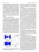
As mentioned in Sec. I, one challenge for three-wave FIR polarimetry and interferometry diagnostics in FRCs is the fringe jump issue due to laser beam refraction. Shown in Fig. 3 are raw IF signal data from shots 104989 (upper left) and 105185 (lower left) of the FIR chord with an impact parame- ter of 0.283 m. In shot 104989, the signal amplitude drops to near zero at ∼2.145 ms, causing the fringe jump problem, i.e., the interferometer phase from one time point to the next will change by an unphysical amount of 2π. The other potential issue is that the small signal maybe contaminated by spurious laser power received (optical cross talk). The isolated fringe jump can be corrected manually, casting some error near the jump time. If frequent fringe jumps occur in the shot or there is serious optical cross talk, the interferometer phase tracking is broken and the data from such shots will have to be abandoned. One way to mitigate this issue is to defocus the laser so that at the detector aperture the laser spot is oversized, effectively increasing the receiving angle. Also the detector is pre-shifted by a small amount in the direction of laser beam refraction
FIG. 3. Raw data of channel 11 located at 0.283 m from two different shots (left) at times of very high but about the same density gradient as shown in the corresponding line-integral density profiles (right).
(opposite to the density gradient direction). With these mea- sures implemented in shot 105185, at ∼1.295 ms the IF signal drop is limited even though the density gradient is the same as in the case of shot 104989, as seen in the line-integral density profiles (right).
In most multi-channel polarimetry and interferometry sys- tems, the receiving optics is arranged in a single plane.5–7 In such systems, the distance from the plasma to the mix- ers is large since the area next to the exit windows is used for beam combiners. Further away the mixers from the plasma, more laser beams offset and more severe signals loss as the beams deviate from the original directions due to refraction. With the double-stacked receiving optics arrangement shown in Fig. 2(a), mixers are very close to the exit windows. This sig- nificantly reduced the distance from the mixers to the plasma center (from ∼2 m to <1.2 m). Subsequently the laser beam refraction effect is mitigated. The complexity for alignment due to this arrangement is negligible. In combination with the defocusing and pre-shift measures mentioned above, most (>90%) of the good plasma shots with line-integral density <3 × 10¹⁹ m−2 are free from the fringe jump problem.
Several measures are implemented to minimize the optical cross talk. The most important is to use absorbers for reflected and scattered laser beams. For example, the detector selects one polarization and reflects the perpendicular polarization, also the power outside the detector aperture is reflected. Small reflection from lens or window surfaces can cause measure- ment errors too. Therefore, all window and lens surfaces are tilted by at least 2◦ so that the reflection can be absorbed not feeding back to the laser cavities to cause extra noises. First surface concave mirrors with long focal lengths [Fig. 1(b)] are used to control the laser beam sizes as they do not create spurious reflection.
As limited bandwidth can cause fringe jumps due to under sampling, the IF signals are digitized at the 30 MHz rate to ensure that the system bandwidth is sufficient to respond to fast changing densities such as the cases of particle refueling by pellets and/or compact-toroid injections or fast moving of high density gradient.
E. EMI shielding and thermal control
The C-2W FRC plasmas are created and translated into the CV by pulsed power discharging circuits. Pulsed power not coupled into the plasmas is on the order of a few MW, which is irradiated in the experimental high bay, resulting in a high level of broadband electro-magnetic interference (EMI), including the bandwidth range (1–5 MHz) of the FIR IF signals. There- fore, it is of most importance to ensure that all signal cables are grounded in a central point in the electronics and con- trol cabinet to avoid any ground loops. It is also important to provide good shielding of the cables, detectors, control equip- ment, etc. and to use high quality line filters and EMI shielded cabinets with a shielding effectiveness of 90 dB or better. To ensure the safe operation of the lasers, an aluminum enclosure is built on the optical table to enclose the lasers and control equipment for EMI shielding. These measures implemented have successfully ensured that the EMI to the FIR system is down to the digitizer bit noise level. For comparison, previous systems can have noise spikes on the order of 1 volt.
