
An Interesting Poster to look at from the Tri Alpha Energy Team in California
P. 1
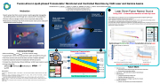
Fusion-driven Liquid-phased Transmutator: Monitored and Controlled Real-time by CAN Laser and Gamma beams
Gerard Mourou2, A. Necas1, T. Tajima1, S. Gales3, K. Hatfield1, M. Leroy4, J. Tanner1 and the Entire TAE Team
Motivation
Spent nuclear fuel from current nuclear reactors generally managed by two distinct policies: once-through (U.S., Sw) and U/Pu recycling (Fr,J)
Policies influence storage duration due to long-lived radionuclides Radiotoxicity and decay heat from stored nuclear waste can be reduced if
1TAE Technologies: 19631 Pauling, Foothill Ranch, CA, 92610, anecas@tae.com 2 Ecole Polytechnique, Route de Saclay, 91128 Palaiseau, France
3 Universite Paris-SUD, 15 Rue Georges Clemenceau, 91400 Orsay, France
4 University of Strasbourg, 4 Rue Blaise Pascal, 67081 Strasbourg, France
2
Laser Driven Fusion Neutron Source
Using CAIL - Coherent Acceleration of Ions by Laser
transmutation assists recycling
Adjust nuclear waste concentration
by laser monitor
1 CANlaserand Gamma beam monitors
• • • • • • •
CAIL: Method to accelerate ions by irradiating nanometric foil with “CAN” laser
2D PIC simulation of laser/foil interaction with EPOCH [4]
Laser is modelled as a Gaussian pulse, linearly polarized, ultrashort (even single-cycle) and ultrahigh contrast
Foil modelled as a solid density plasma of deuterons and electrons: ne >> ncritical
Foil is nanometric to satisfy requirement: foil thickness < skin depth allowing the laser to partially penetrate the foil Ponderomotive force drives electrons out of the rear side of foil and ions interact via the electrostatic potential. [3] Experiments [2] support simulations
Theoretical max. energy (a=4)
Deuteron energy [keV]
Optimal target thickness for efficient Acceleration of Ions by Laser Deuteron energy vs. thickness of
foil
target thickness [normalized to laser intensity]
Optimum parameters (sweet-spot) for ion acceleration
Neutronics -- externally driven system: MCNP/SCALE Wall material:
Corrosion assisted by molten salt
Radiation damage by neutrons
High temperature, fatigue (e.g. tellurium creep)
Nuclear chemistry:
Molten salt chemistry and chemical separation
Nuclear waste
and FLiBe solution In
3
1
Parameter
Value
Intensity*, W/cm2
5x10¹⁷
Pulse length, fs
45
Beam width, mm
3.6
Laser energy, mJ
6
Foil thickness, nm
10
Skin depth, nm
25.3
Electron density 1/cc
4.4x10²²
Critical density 1/cc
1x10²¹
Rep rate, kHz
10
1
2 Laser driven fusion neutrons
G. Mourou
Liquid-phased molten FLiBe salt (operates under atmospheric pressure)
Real-time monitor and control (by laser and laser Compton gamma)
Subcritical operation (neutron multiplication driven by source)
Compact low intensity laser driven (CAN laser +CAIL) fusion neutron source
Energy catapulting:
100 keV/D+14 MeV/fusion200 MeV/fission x keff=0.98
BIBLIOGRAPHY
(1) Mourou, G., Brocklesby, B., Tajima, T. and Limpert, J., The future is fibre accelerators. Nature Photonics, 7(4), p.258 (2013).
(2) Steinke, S., Henig, A., Schnürer, M., Sokollik, T., Nickles, P.V., Jung, D., Kiefer, D., Hörlein, R., Schreiber, J., Tajima, T. and Yan, X.Q., Efficient ion acceleration by collective
laser-driven electron dynamics with ultra-thin foil targets. Laser and Particle Beams, 28(1), pp.215-221 (2010).
(3) Yan, X. Q., et al. "Theory of laser ion acceleration from a foil target of nanometer thickness." Applied Physics B 98.4
(2010): 711-721.
(4) Arber, T. D., et al. "Contemporary particle-in-cell approach to laser-plasma modelling." Plasma Physics and Controlled Fusion 57.11 (2015): 113001.
Transmuted nuclear waste
chemically separated out
4
Conceptual Design
3
Nuclear Waste and FLiBe solution In
Numerical Transmutator
MCNP/CINDER90
4
Transmutated nuclear waste chemically seprated Out
Fission Products
39.2 Kg
Plutonium 20.76 Kg
Am 2.53 Kg Np 13.84 Kg
Cm 283.8 Kg
Minor actinide σfission >> σcapture at source neutron energy
R2
R1
Graphite reflector
1 Year study - 100MW
Input1 year burnOutput
FP Pu Am Np Cm
Americium 6.6 Kg
Neptunium 24.86 Kg
Curium 328.56 Kg
370
360
350
340
330
320
310
300
290
280
270
Steinke (2010); a0=5
Neutron source isotropic at R=0
GEOMETRY
R1 =50cm
R2 = 80.48 cm
Tank axial length=2 m
Initial tank composition
ZAID
Mass [g]
ZAID
Mass [g]
Americium
Curium
95241
4440
96242
576
95242
141.3
96243
3645
95243
2018
96244
284000
Neptunium
96245
36900
93237
24860
96246
3357
FLiBe [LiF-BeF2]
96247
47.27
3007
510100
96248
3.258
4009
372000
9019
3258000
Future Work
Neutron source:
Proof-of-Principle experiments with laser foil acceleration Electrostatic accelerator viability
0 1 2 3 4 5 6 7 8 9 10111213141516171819202122232425262728293031323334353637383940414243444546474849505152
Week
Total TRU burn 39.4 kg (11%)0.4 kg/MW
Mass (Kg)
Energy
Deuteron distribution
| 1 |
