
Fusion-driven Liquid-phased Transmutator: Monitored and Controlled Real-time by CAN Laser and Gamma beams
P. 1
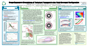
Cross-Separatrix Simulations of Turbulent Transport in the Field-Reversed Configuration
Calvin K. Lau1, Daniel Fulton1, Jian Bao2, Zhihong Lin2, Toshiki Tajima1,2, Lothar Schmitz1,3, and the TAE Team1
more questions? email me at clau@tae.com
n Drift-wave linearly stable in FRC core
n IonfiniteLarmor(FLR)effects
n Magneticwell(radiallyincreasingB-field)
n Electron parallel dynamics (short circuiting effect) n Noinstabilityfoundforkζρe<0.3,η=1,κ<5*
n Unstable SOL
n Destabilizing: electron-temperature gradient, density
gradient, barely trapped electrons
n Stabilizing: higher temperature ratio, FLR, ion temperature gradient
n Linear thresholds are consistent with experimentally measured fluctuation thresholds
SOL : 1.10≤r/Rs≤1.22 core : 0.82≤r/Rs≤0.87
(R0/Cs = 2.5 μs
κ=R0/Ln)
Fig: (TOP) Fluctuation spectrum from experiment and (BOTTOM) linear dispersion from simulation. SOL instability can be driven by pressure drives of varying strengths, but no instability is found for the core region.
n Electrostatic particle-in-cell turbulence code (ANC) cross-separatrixsimulationsofmultipletoroidalmodes currentlyusinggyrokineticdeuterons,adiabaticelectrons
n Nonlinear simulations show inverse cascade in SOL
consistentw/simulationslimitedtoSOL,cascadedueto
mode-mode coupling from unstable shorter wavelength
modes to stable longer wavelength modes
resulting SOL spectrum shape (green line in plot) matches
decreasing trend measured in experiment (green points in plot)
n Fluctuations spread from unstable SOL to stable core consistent w/ single-mode simulations, radial spreading
due to physical coupling via nonlocal gyroradius effects
coreà no inherent instability found, fluctuations sourced
from SOL leading to larger deviation in fluctuation level over
time (shaded red region in plot)
resulting core spectrum magnitude (green line in plot) matches
magnitude measured in experiment (green points in plot)
Fig (RIGHT): Electrostatic potential is shown as viewed along the machine axis at the center of the confinement vessel for two distinct times. The dashed line represents the separatrix, and the grey region represents the null-point which is excluded from the simulation domain for gyrokinetic validity. The inverse cascade from shorter to longer wavelength can be seen in the change in structure between the two times. Note that the structures within the core is much smaller than in SOL.
Fig (ABOVE): Fluctuation spectra from simulation are consistent with experiments. Lines and shaded regions correspond to simulation results: lines are mean fluctuation levels and shaded regions represent deviation over time integrated. Points are from experimental measurements via DBS.
Lineargrowthphase
1 TAE Technologies, Inc., 19631 Pauling, Foothill Ranch, CA 92610 2 UNIVERSITY OF CALIFORNIA, IRVINE, Irvine, CA 92697
3UNIVERSITY OF CALIFORNIA, LOS ANGELES, Los Angeles, CA 90095
n Cross-separatrix simulations of single mode
w/gyrokineticdeuteron,adiabaticelectrons
n Linear:instabilityonlyformsinSOL
n Nonlinear: fluctuations spread to core n Saturationlevelconsistentfrom
sim. to exp. at similar wavenumbers
n simulation: eφ/Te = ~0.05
n experiment: ñ/n = 0.01~0.1
n Core saturates at ~10x lower
Post-saturation
A
B
Fig (BELOW): 3D visualization of instability forming in the SOL. The purple shell represents the separatrix surface. The annular slices correspond to different positions of Z, from the end of the device to the center of the confinement vessel.
Fig: Mode structures during (A) linear growth and (B) after saturation. The dashed line is the separatrix.The fluctuations are seen to spread into the core after saturation.
ACKNOWLEDGEMENTS
Simulations used the resources of DOE Office of Science User Facilities: National Energy Research Scientific Computing Center (DOE Contract No. DE- AC02-05CH11231) and Innovative and Novel Computational Impact on Theory and Experiment (INCITE) program at Argonne Leadership Computing Facility at Argonne National Laboratory (DOE Contract No. DE-AC02-06CH11357). Portions of this work were carried out at University of California, Irvine with the support of the Norman Rostoker Fellowship (Grant No. TAE-200441).
Fig: (TOP) Radial-time history shows instability first forms in SOL, then spreads across separatrix into core before saturation. (BOTTOM) Ratio of fluctuation in SOL to core is plotted against time. Nonlinear spreading leads to the core fluctuations being 10x lower than SOL at saturation.
SEE ALSO
amplitude than SOL
APS-DPP 2018 / Portland, Oregon / November 5-8, 2018
n
Recent publications
D. Fulton et al,
Phys. Plasma 23, 056111 (2016)
D. Fulton et al,
Phys. Plasma 23, 012509 (2016)
L. Schmitz et al,
Nat. Comm. 7, 13860 (2016)
C.K. Lau et al,
Phys. Plasma 24, 082512 (2017)
C.K. Lau,
UCI Doctoral Thesis (2017)
Other publications/presentations by TAE
https://tae.com/research- library
Local linear dispersion
Experimental measurements
via GTC simulations via Doppler Backscatter (DBS)
density fluctuations : ñ/n
n
| 1 |
