
APS-DPP18_ftnaka_(004)_tm2_ta_tr
P. 1
•
•
CT injector (MCPG) consists of a set of coaxial cylindrical electrodes, iron-core bias coil, puff valves, and pre-ionization (PI)system.
o A plasma is generated between electrodes and accelerated by J x B Lorentz self-force.
o The accelerated plasmoid is captured by the bias field, and its toroidal current is induced.
o A compact toroid (CT), spheromak-like plasmoid, is ejected from MCPG.
Two puff valves and two mini-guns are mounted on the cross- section denoted by the green line.
o These ports are mounted tangentially for a uniform gas distribution.
o Gas is injected into mini-gun passively.
~ -10 kV
0
!=14 1−1
B%
ln(A%&) − ln(ln( 1 + 1⁄0))
•
• •
1. INTRODUCTION
4.1. MINI-GUN EXPERIMENTS
Apply Voltage
Breakdown
Puffstart
Typical operation.
The charging voltage is 3.3 kV and the puff duration is 1.0 ms.
Breakdown timing is defined as the time from puff trigger to initialization of current.
• •
4.2. INNER ELECTRODE AND GAS PRESSURE EFFECTS ON PLASMA
•
• •
A magnetized coaxial plasma gun (MCPG) is one of the devices used to generate and accelerate a compact toroid (CT) with a spheromak-like magnetic configuration.
o If you are interested in CT injection on the C-2W, see also PP.11.00095 and PP11.00096
In order to expand the CT operating range, the MCPG introduced an “iron-core bias coil” and “miniature gun”*1
In this poster, we show the optimization of pre-ionization (PI) system, miniature gun (mini-gun), for decreasing trailinggasthatpotentiallycoolsthetargetplasma.
o SimulationofgasflowintheCTinjectorandexperimentsofmini-gunwiththreedifferentinnerelectrodes.
o ComparebothresultsviaPaschen’slaw
o Dependenceofgaspuffingpressureandinnerelectrodesizeontheinductanceandresistanceofthe
IGBT (8 series)
G
6Ω
30 μH
Breakdown timing becomes faster with thicker electrode (and also lower gas pressure).
Gas diffusion along z-axis is expected to be suppressed with faster breakdown times.
150μs
179 μs
Breakdown timing at each Inner electrodes and gas puffing pressure.
Experiments and Simulation are Consistent!
Comparisons of experiments and the simulation through Paschen’s law.
The top one is experimental results of breakdown timing.
The bottom is modified Paschen’s curve with simulation results. The highlighted area shows the pressure between electrodes from the simulation at the time range in the figure.
plasma ejected from the mini-gun.
*1T. Edo et al., J. Plasma Fusion Res. 13, 3405062 (2018)
Innerelectrode
10
2. CT INJECTOR
(MAGNETIZED COAXIAL PLASMA GUN)
•
3. GAS FLOW SIMULATION by OpenFOAM®
Mini-gun
SUMMARY
Inlet (Orifice: 1mm) Wall
Outlet
Model geometry for simulation
• Cut MCPG near the puff valves
• One z-cross section is Outlet, another is wall.
Estimation of gas inlet velocity
Particle number
N
>⁄2
9 = 22.4 × ×
Initial values of gas inlet velocity are estimated from enclosed particle numbers.
Time
Flow Turbulence
Turbulence Model
Mesh size
The # of cell Material
Gas inlet velocity
End time Δt
Calculation time
Transient Incompressible RANS
Realizable k-ε
0.5 x 1.0 x 1.0 (Unit: mm)
- 105 Deuterium
1.2, 0.74 km/s (40, 25 psia)
2 ms 1 μs
2 hours
• •
•
•
The simulation and experiments were compared via Paschen’s law.
The flow simulation was consistent with experiments. It can also be applied to other models, in particular, the new CT injector for C-2W.
o The simulation could obtain optimum gas conditions for mini-gun/CTI.
The experiment result indicated the amount of plasma depended on gas puffing pressure
and inner electrode size.
o Ionization efficiency would be increased by more initial plasma generated from the mini- gun.
We will investigate/evaluate this PI effect on CT performance.
•
Gas puffing pressure [psia]
25 40
Particle number [x 1019]
3.13 5.01
Flow velocity [m/s]
741 1186
>?
S: cross-sectional vector area Particle number and flow velocity
Outer Electrode (I.D. Φ 16)
Inner Electrode (O.D. Φ 6, 8, 10)
Coefficient
A*3 [(Torr • cm)-1]
Value
5.1 124.8 0.8
o At 40 psi, it was expected from the simulation to start discharging at around 1 ms
o 25 psi, at around 2 ms.
o Mini-gun experimentally got breakdown
at a similar time.
Optimum conditions can be predicted by the simulation.
Mini-gun Voltage
0–2 ms
25 psi
1–2 ms
40 psi
Cross section of gas injection. Color plot shows flow velocity from a simulation result
Comparison of Paschen’s curves
Estimated plasma inductance and resistance
1 ∆A
9 C
depending on gas pressure
• •
•
•
Flow rate
Q
N : Avogadro constant A
Flow velocity
U
Plotting point of simulation results (the green star). The color and contour plots shows electric field between electrodes
The right figure shows results of simulation at the star point.
This star point is a location of electric field concentration. o Breakdown is expected to start at this point.
The pressure is independent of the inner electrode size. Only depends on the gas puffing pressure.
o However, same pressure means the enclosed particle number into mini-gun increases with thinner electrode.
Δt: puff duration (1 ms)
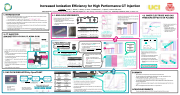
Increased Ionization Efficiency for High Performance CT Injection
B =
F. Tanaka1, T. Asai1, T. Roche2, I. Allfrey2, H. Gota2, T. Matsumoto2,3, T. Tajima2,3, and the TAE team2
1Nihon University, Chiyoda-ku, Tokyo 101-8308, Japan, 2TAE Technologies, Inc., 19631 Pauling, Foothill Ranch, CA 92610, USA, 3University of California, Irvine, CA 92697, USA
0 100 [mm]
Schematic view of magnetized coaxial plasma gun
100 [mm]
miniature gun
+3.3 kV
puff valve
5. PASCHEN’S LAW
•
•
Traditional Paschen’s law is for parallel electrodes, however, this PI system is cylindrical.
o The formula was modified by Z. Wang et al.*3 for cylindrical electrodes.
Coefficients; A, B and γ, are selected for Deuterium (puffing gas) and Stainless Steel (material of electrodes).
Clearly decrease depending on pressure
*Background pressure: ~ 10-7 Torr
The flow velocity increases with thinner electrode due to higher conductance.
•
We have made new mini-gun with three different inner electrodes; diameter are 6, 8, and 10 mm.
o It is expected the discharge condition will be changed by different electrodes.
o Theinnerelectrodecanbeeasilyreplacedbecauseof itsingenuity.
!" =
B%&
ln(A%&) − ln(ln( 1 + 1⁄0))
for Parallel Electrodes
rin
d rout
G757RS = !T⁄DURV
G=G−G WSR"UR 757RS T2XT627
Plasma inductance and resistance are estimated from the above formula as time- independent.
The inductance clearly decreases depending on gas pressure (five times difference).
The resistance result shows that plasma density depends on inner electrode diameter.
o Becausethereismoreinitialgasinsmaller electrode.
The amount of plasma might depend on gas pressure and electrode size.
"
23
1 23
1 567
Ceramic
Outer electrode Cross sectional area
Specification of each inner electrode
Rise time is changed ~ 5 μs
25psi
Geometry of mini-gun
Inner electrodes
*2Z. Wang et al., Rev. Sci. Instrum. 76, 33501 (2005)
Simulation conditions
*3D. J. Rode, phys. Rev. 104, 273 (1956)
for Cylindrical Electrodes*2
Coefficients for Deuterium and SS
•
•
Experiments and the flow simulation are consistent!
B*
3
[V / (Torr • cm)]
γ
+3.3kV 52μF
5 kΩ
Innerelectrode diameter [mm]
Cross sectional area [mm2] Inductance [nH] Resistance [mΩ]
6 8
173 151
9.81 6.93 4.70
40 psi
Dischargecircuitformini-gun
•
The driven currents are affected by the gas pressure and inner electrodes size.
o Obviously,therisetime depends on the gas pressure.
o Thepeakcurrentat40psiis higher than it at 25 psi.
2.75 1.55
0.990
Averaged driven current with inner electrode; 6 and 10 mm, and gas puffing pressure; 40 and 25 psi.
D≈!F(HIJ −HILJ) (R4≫4P) GKLM Q
Analytic solution for LCR circuit
123
Time Gas Mesh Solution Model
U [mm/ms]
Time evolution of pressure and velocity at the star point
ACKNOWLEDGMENTS
This work was partially supported by 2018/2019 Overseas Scholarship at Nihon university.
P =G×YI[−P
T2XT627
WSR"UR 757RS
X2"Z
| 1 |
