
An Interesting Poster to look at from the Tri Alpha Energy Team in California
P. 1
Figures show plasma characteristics of C-2W discharge: Excluded flux radius (Rs) (top), central detectors from far-infrared interferometer (middle), and SEEs detectors from neutral beam 1 (bottom)
S ~ ne (x, y, z, t)
The SEE signal is dependent on
the incoming neutral beam, its interaction with plasma density, and the magnetic field near the wall.
[Bottom Left] The center of the beam in terms of r and z, where r = (x2 + y2)0.5
Eight 15 keV neutral beam injectors are installed on C-2W; each has a array of secondary electron emission (SEE) detectors to measure the beam profile and attenuation
MHD stability control has been established with electrode biasing on the inner and outer divertors
Without stability control, C-2W has two major MHD instabilities that cause bulk plasma motion, detrimental to plasma
confinement and lifetime
The SEE detector arrays can be leveraged use estimate beam attenuation to estimate plasma motion
During n = 1 mode activity, the plasma rotates in the x-y plane clockwise, whereas n = 2 causes a drift and rotation in the courter-clockwise direction
Analysis needs to be vetted with other diagnostic measurements (magnetics, FIR, etc.)
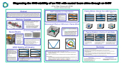
Diagnosing the MHD stability of an FRC with neutral beam shine through on C-2W
Abstract
Heating, current drive, and partial fueling from neutral beam injection are essential to sustainment of C-2W field-reversed configuration (FRC) plasmas.1 Eight beams are injected off-axis, just outside of the axial center of the FRC. After traversing the plasma, the uncaptured components of each beam interface with a secondary electron emission (SEE) detector array installed in the beam dump and the shine through can be measured.2 Since beam capture is dependent on plasma density, any changes in density within the beam path are reflected in the measurement. Due to the geometry of beam injection, changes outside of the FRC core can be monitored. During the n = 1 and 2 instabilities, the plasma wobbles and the density of the plasma in the beam path changes. Without effective stability control, it has been seen that when beam shinethrough decreases, the FRC plasma appears to start shrinking and the n = 1 instability grows, after which the FRC dies out due to the instability or keeps rotating with somewhat reduced/saturated mode growth.
Machine Overview
J.B. Titus, R. Magee, S. Korepanov and the TAE TEAM TAE Technologies, Inc., 19631 Pauling, Foothill Ranch, CA 92610
MHD Instabilities in C-2W Plasmas n = 1, 2 are prominent without stability control via electrode biasing
Instability characteristics: mode amplitude (top), phase (middle), and frequency from Mirnov probe arrays (bottom)
[Left] Example of a strong n = 1 instability, which rotates clockwise
[Right] Example of a strong n = 2 instability, which rotates counter- clockwise
Measurement Effects on SEEs due to Plasma Motion
Plasma Motion Inferred from SEE Detectors
Neutral Beams
The C-2W neutral beams: based on C-2U injectors with modifications to the ion source and power supplies for 30 ms pulses
30% more power
Four arc-discharge
plasma sources
3-electrode ion-optical system with multi- aperture slit optics for beam formation
[Left] Neutral beam injection into SEEs detector arrays with a plasma centered in the confinement vessel.
If a plasma moves in a particular direction, the density of the plasma changes and the SEE detector signal changes. For each isolated direction, a portion of the signal increases for a subset of beams and the signal decreases for the other subset.
Plasma Rotation in Terms of r and theta
C-2W experiment:1 an advanced, beam driven field-reversed configuration (FRC)3 plasma
Eight 15 keV neutral beams
Results from C-2W experiment:
neutral beam pulse duration was correlated to plasma lifetime and critical for sustainment4
Inner and outer divertor biasing has lead to control of both n = 1 and 2 instabilities
Secondary Electron Emission Detectors (SEE)
In three dimensions:
MHD Stability with biasing
Neutral Beam
Time [ms]
Time [ms]
If the FRC is assumed to be a cylinder, r is independent of z and the density can be assumed to increasing with decreasing r
[Bottom Right] A centered plasma inside the confinement vessel with a neutral beam passing through it. Finding the subsets:
To figure out whether an array will see a positive or negative change for each isolated direction, the change in line-average density change was simulated for a moving plasma.
If the plasma moves in the + y direction, n dl is lost while n dl is gained. This is a net loss, so the line- average density seen by the detector decreases and the signal decreases.
References
1M. W. Binderbauer et al. Recent Breakthroughs on C-2U: Normans Legacy. AIP Conference Proceedings, 1721(1):030003, 2016
2J.B.Titus et al. RSI, 89, 10I123 (2018) 3M.Tuszewski.Nucl.Fusion,28(11):2033,1988.
4H. Gota et al. Nucl. Fusion, 57(11):116021, 2017
Acknowledgements
We thank our shareholders for their support and trust, and all fellow TAE staff for their dedication, excellent work,andextraefforts.
Collimator
5 15 14 13 5 12 11 10 10 11 126 13 14156
Mo Target
11 22
7 88 99
Beam Dump
[Left] Collimator: diameter of 1.0 mm; length of 9.0 mm
Beam neutrals interact with a molybdenum target, producing a current of
secondary electrons, which is proportional to neutral-beam particle flux
[Right] Two beams converge onto one beam dump
Each beam is centered on an array of SEE detectors
Nine detectors in the vertical direction and seven detectors in the horizontal direction, crossing at detector 5
Detectors 5 and 15, 13 and 14 share the same aperture
Neutral Beam path through the CV
Confinement Vessel
[Left] UNBIASED A plasma discharge with a strong instability. The shinethrough modulates while the plasma wobbles due to the instability
[Right]BIASEDAstableplasmadischarge.Theshinethroughoftheneutralbeamincrease only when the plasma starts to decay
33 44
7
Plasma movement
In the case with low mode activity, the plasma remains stationary
In the case with large n=1 mode activity, the plasma oscillates in the x and y plane and rotates clockwise
Summary
In the case with large n=2 mode activity, the plasma oscillates in the x and y plane and rotates counter clockwise
Stable
Strong n = 1
Strong n = 2
| 1 |
