
LSchmitz_APS_2018_TAE
P. 1
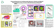
 Density Fluctuation Wavenumber Spectrum ñ(kq) via a dedicated receive horn
2 Typically requires sin(φ0 ) ≤ knax fL ≤ 3-5o
Heterodyne U-Band Receiver
(2 ch, dedicated DBS and
CPS Paths)
DBS/CPS can probe
toroidal wavenumbers -1
X,Y Plane Ray Trajectories
Ray Tajectories for varying axial mismatch angle φ
kq =1-15 cm (via adjusting the toroidal launch angle). Axial FRC contraction cau- ses a finite axial mismatch angle that will be compensated via two-axis adjust- ment of the focusing mirror.
3o Launch
42473 2.5 ms
48 GHz
40 GHz
33 GHz
U
Ka
40
0 L
CPS 26-40 GHz X-mode receive
CPS X-mode receive (40-60 GHz)
O-mode 26-40 GHz DBS launch/receive
26-60 GHz tunable Ka, U-Band sources cover densities 0.83 - 4.4x10¹⁹ m-3
X-mode. 47.7 GHz 42473
Two-axis alignment of focusing mirror via dual stepper motor control
40 20 0
-20 -40
2
1
-10
-20
-30
-40
-50
-60 -70
φ =0
φ =2o
φ =4o
φ =8o
Turning point (cutoff)
-50050 X (cm)
-40
0
x (cm)
20
7.3
12
0
-50
-40 -20
1e13
0 20 Z (cm)
40
60
3e13
O-mode DBS launch/ receive (40-60GHz)
Rs
-20
-2 0 2.7
z (cm)
Advanced Diagnostics for the Wavenumber Spectrum of Density and Magnetic Field Fluctuations in the C-2U and C-2W Field-Reversed Configurations
L. Schmitz1,2, B. Deng1, H. Gota1, M.C. Thompson1, C. Lau1, D. Fulton1, Z. Lin3, Y. Petrov4, R. Harvey4,T. Tajima1,3, M. Binderbauer1, and the TAE Team 1TAE Technologies, Inc., 19631 Pauling, Foothill Ranch, CA 92610, 2University of California Los Angeles, 3University of California Irvine, 4Comp-X, San Diego, CA
Abstract: An advanced multi-channel combined Doppler Back-
scattering (DBS)/Cross-Polarization (CPS)[1] diagnostic for the C-
2W Field-Reversed Configuration (FRC) will be discussed, allowing
simultaneous measurements of the wavenumber spectrum of Incident/scattered electric field Eii, Es: (a) density fluctuation and magnetic fluctuations. Cross-correlation Induced current J (i):
originate essentially from the same scattering volume. GENRAY ray tracing predicts that magnetic fluctuations with 2 ≤ krs ≤ 50 can be
GENRAY ray tracing of incident/scattered O-mode and X-mode CPS return
FRC core plasma inside separatrix: Decreased fluctuation level at low kρs
Low-k ion modes reduced by almosttwoordersofmagnitude in the FRC core
Summary
• A new 4-channel combination Doppler Backscattering (DBS) and Cross-Polarization Scattering (CPS) Diagnostic for the C-2W FRC is described.
• CPS has great potential for wavenumber-resolved magnetic field fluctuation measurements in C-2W, guided by GENRAY ray-tracing and (soon) full-wave code calculations.
• DBS/CPS: Need to control the axial mismatch angle due to axial contraction of the FRC; this will be accomplished via a two-axis mount for the focusing mirror (under development for C-2W).
• FRC Core: No ion-scale (large-scale) turbulence; near classical ion transport. SOL: Moderate, multi- scale SOL turbulence observed/predicted by gyrokinetic (GTC) simulations (driven by the radial density/electron temperature gradients).
Cross-Polarization Scattering (CPS): Measuring Magnetic Fluctuations (Br)
X-mode and O-mode cut-off locations for different FRC parameters
analysis on ñ and Br should be possible as the backscattered O- 40 mode DBS return and the backscattered X-mode CPS signal 2$'
T =1keV 40 tot
Be=0.1T RRFR 20
42 GHz 40 O (DBS)
X (CPS)
20
0
-20
-40
(b)
28 GHz
O (DBS)
X (CPS)
50
O-mode Launch
0i
accessed in the FRC core and scrape-off layer (SOL). DBS data iεω2 ñ ω + ! -
fco
R0 Rs
−∇× ∇×E +$ωi ' 1− σ E =−iμ ∂J(i)
( s)&%c)(&%iεω)(s o∂t 20
0
f R0 cx
J(i)= 0 pe E+ i σσE×B/B i2,i.k
turbulence in the FRC core [2]. Global gyrokinetic simulations kS kθ 0
attribute core stability to Finite Larmor radius effects, short field-line ωI,kI (b)
connection length, and favorable magnetic field gradient. Transport The second (highlighted) term describes ζ
analysis indicates near-classical core ion thermal diffusivity. In the induced current in the opposite 40
from the C-2U FRC already show the absence of ion-scale density
ωi ne εoωpe I
f ce
fce
R0 Rs fce
-20
Rs
contrast, multi-scale turbulence including short-scale electron polarization and is proportional to Br
Back-scattered X-mode CPS return
Back-scattered X-mode CPS return
modes is observed via DBS in the mirror-confined SOL plasma, also Polarizer
Launch angle ζ= 4o, 8o, 15o Probed kθ: 1.3, 5.2, 10.7 cm-1
Launch angle ζ= 4o, 8o, 15o Probed kθ: 2.1, 4.5, 9.2 cm-1
20 [1] X.L. Zou et al., Phys. Rev. Lett. 75 1090-93 (1991). overlap (as wpe >> wce). Hence the CPS DBS ωs=ωi-kθvExB 0
f co
in agreement with global gyrokinetic simulations which predict X-Mode
f cx
unstabledrift-interchangemodesforkr >1.5. In C-2W, the trajectories of launched and O-Mode CPS receive
s backscattered X-mode and O-mode nearly
[2] L. Schmitz et al., Nature Comm. 7 13860 (2016). (O-mode) component can be easily Launch/ k =k -k (c)
Ttot=10keV Be=0.5T
Doppler Backscattering (DBS) Provides the Toroidal separated out via polarizers and detected Receive s i θ 60
"ˆ (ˆ $ r0 E (ω , k ) = k × k × E )
−x2/a2 e
−y2/a2y −i(ω +ω −ω )t
0
20 40 R (cm)
60
s s s #s s i%16π4 aa x
y
$− n x d I / d s ~ n! 2 ( k , s ) e #
2
0 ' &
ne (cm-3) 2.7e13 2.2e13 1.6e13 1.0e13 0.4e13
Ray Trajectories and Electron Density 80
60 40 20
0 -20 -40 -60 -80
80 60 40 20
DBS/CPS Diagnostic Positioning on C-2W
DBS/CPS Beam Optics - Lensed Scalar Horns with Wire Grid Polarizers; Parabolic Adjustable Focusing Mirror
0
ne (cm-3) 2e13
n
Refractive Index Components vs. X, R, and f;
" k 2a2sin2(φ )%
Poloidal mismatch angle f0: k • B = cos(π /2-φ ) i 0
∫ dω dtdk dx n! ω k
n n ((nn) x
e
i(k +k −k )x i n s
−iω R /c
e e
e
sd ) Refractive index along Launched/Back-scattered Rays
i n s
40 20
0
fco
f cx
Ttot=3keV -40 Be=0.2T (a)
-40
-10
20
50 -40 O-mode
Launch
-10
x (cm)
20
Probing Fluctuations inside the Separatrix
Probing Fluctuations in the Scape-Off Layer
x (cm)
L
L
L
L
ne (1019 m-3)
y (cm)
X (cm)
Y (cm)
R (cm)
f (GHz)
f (GHz)
f (GHz)
y (cm)
y (cm)
| 1 |
