
APS 2018
P. 1
current density, and Te.
energy analyzer bolometer
Debye potential is roughly 1 Te for this shot. .5 0
Abstract
FRC Core
Cylindrical axis (meters)
connection to signal cables
current sensor electron grid
ion grid
attenuationgrid
high energy ions
low energy ions
electrons
springs isolate the crystal from vibration
Incident power, Q
V = IpR
!!= ! ×! !"#
mounting structure
alumina baseplate
current sensor
secondary electrons
e. grid
!(x)
ion grid
atten. grid
Energy Analyzer Construction
Biased Grids Repel Certain Particles Before they Reach a Current Sensor
2. ! "!"#$
( = $% &
)*+,-.
%&
' (& ) *)
pyroelectric crystal
LiTaO3 crystal
Pyroelectric LiTaO3 crystal, mounted on springs to isolate it from vibration
Crystal’s permanent polarization varies with temperature, causing polarization current proportional to incident power density.
Broad frequency response (100-200 kHz) and can withstand high heat loads (20 MW/m2).
The C-2W Experiment
Electron Heat Confinement on Open Field Lines: Theory
Electron Heat Confinement on Open Field Lines: Experiment
Measurement of the Debye sheath potential
FRC core surrounded by a scrape-off layer on open field lines.
Open field lines have a mirror region at either end of the central vessel (CV), then expand ~30x and connect to electrode plates in the divertor vessels.
1.5 1
.5 0
CV
(a)
Ambipolar Potential
Energy per Ion, "
Energy Analyzer Signal
Ion Grid I-V Trace
1.5 Open field lines connect only in outer divertor 1
for plasma formation (a), then expand during a
shot to connect to inner divertor electrodes (b). .5
0
FRC Core
SOL Mirror
v⟂
|| ||
core ions
Outer divertor electrode plates
energy analyzer used for the measurement
C-2W’s End-Loss Diagnostics
plasma gun
CV
C-2W’s open field lines end on sets of concentric electrodes in the divertors.
These electrodes are instrumented with an array of particle energy analyzers and bolometers [2].
The diagnostics measure power density, ion energy distribution, ion and electron
Confinement Vessel
i
φcore = (4-5) x Te
Inner Divertor
Outer Divertor
Energy Analyzer Signal
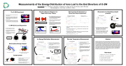
We report on measurements of the ion energy distribution function (IEDF) of ions lost from the scrapeoff layer (SOL) of the C-2W experiment [1] at TAE technologies. C-2W consists of a field reversed configuration (FRC) core plasma surrounded by a mirror-confined SOL on open field lines. The open field lines extend past a mirror at either end of the central vessel and then expand by a factor of Bmax/Bmin~30 into large divertor vessels where they terminate on sets of concentric
circular electrode plates. The expanding magnetic field, and large pumping speed in the divertors is designed to impede cold electrons generated at the edge of the machine from flowing back into the central vessel. This should allow an ambipolar potential to develop inside the mirror-confined region of the SOL and reduce electron heat transport out of the region. We used electrostatic ion energy analyzers mounted on the divertor electrode plates [2] to measure a drifting Maxwellian shaped IEDF. The results show that an ambipolar potential develops in the central vessel and give insight into electron heat transport on the SOL.
References
1. M. Binderbauer et al., AIP Conf. Proc. 1721, 030003 (2016). 2. M. Griswold et al., Rev. Sci. Instr.. 89, 10J110 (2018).
3. R. F. Post, Nucl. Fusion 27, 1579 (1987).
4. L. S. Hall, Nucl. Fusion 17, 1579 (1977)
5. D. D. Ryutov, Fusion Sci. Technol. 47, 148 (2005). 6. S. Gupta et al., submitted for publication (2018)
Electrostatic Energy Analyzer
Pyrobolometer
Ion Grid I-V Trace
Measurements of the Energy Distribution of Ions Lost to the End Divertors of C-2W
Formation Section
be used to determine the sheath potential.
1 SOL Mirror
0
FRC Core
10
loss cone boundary
Inner Divertor
SOL Mirror
Formation Section
Electrodes
Outer Divertor
v⟂
(b) vv
Electrodes
5
Cylindrical axis (meters)
Ion Loss Cone
Electron Loss Cone
Inner Divertor
φs = (1-2) x Te
Outer Divertor
Inner Divertor
Formation Section
Electrodes
Outer Divertor
f
Plasma Potential
M. E. Griswold, M. C. Thompson, S. Putvinski, P. Yushmanov, K. Knapp, B. Koop, W. Thornton, and the TAE Team Tae Technologies, Inc., 19631 Pauling, Foothill Ranch, CA 92610
Radius (meters)
Radius (meters) Radius (meters)
loss cone boundary with positive ambipolar potential
Ion Energy Distribution
Ti
(4-5) x Te
Ion Energy Distribution Measurement
Initial results suggest C-2W has good electron heat confinement on open field lines.
Gas puff 3ms before the shot from plasma gun (at the center of the outer divertor electrode plates) creates a cold ion component accelerated only in the Debye sheath.
This cold component is visible as a low energy
feature in the ion energy distribution, and can 1.5
Energy Analyzer Signal
Electron grid set to -600V to repel all electrons
Ion current density is interpolated from intervals of constant 0V ion grid bias between each triangle wave voltage sweep.
An ion grid I-V trace can be constructed from each upsweep or downsweep of the grid voltage.
Ion energy distribution is calculated here from the first ion grid upsweep (highlighted in red).
Ion grid set to 0V, the analyzer collects net current from electrons and ions.
Electron grid set to base voltage of -30V, needed to suppress secondary electrons from the current sensor.
A single sweep of the electron grid from -30V to -120V and back gives two measurements of the electron temperature (one upsweep and one downsweep, marked with red/black dashed lines).
Imperfections in the grid voltage sweep are due to an under-powered amplifier. A new amplifier has been ordered and should improve the measurement.
Comparison to Te in the Core
E
divertor electrodes
mirror plug
z
Measurements from a dedicated experiment (not the same shot) suggest a debye sheath potential of only ~ 1 Te at the wall.
Electron energy lost per ion, ηe ~ 4-8.
Electron Temperature Measurement
In an hypothetical isolated mirror (with no net current flow), an ambipolar electric potential modifies the loss cone so electrons are lost at the same rate as ions. Thermal energy carried away by electrons is only (5-6) Te per ion that is lost [3,4].
Cold electrons from the edge can destroy ambipolar confinement, leading to free-streaming electron losses of ~40 Te per ion.
Expanding-field divertors, like those on C-2W. are predicted to spread out the potential drop, reducing the potential in the debye sheath [5,6]. This reduces the electric field, and should reduce arcing at the plasma-material interface.
e
ɸ debye ~ 60V
cold ions from gas puff
$
1.!=#$% !"'()( % # "
!"∝" #%(")
Ion Energy Distribution
φ
Core ambipolar potential of 3-4 T e
divertor electrode plates.
, measured from ion drift energy at the
!
! #!
( #$%h ' = )*!"#$ )
Electron Temperature I-V Traces
| 1 |
