
An Interesting Poster to look at from the Tri Alpha Energy Team in California
P. 1
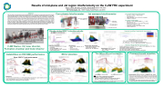
Results of mid-plane and Jet region interferometry on the C-2W FRC experiment
Roger J Smith, Bihe Deng, Eli Parke, Michael Beall and the TAE Team
TAE Technologies, Inc., 19631 Pauling, Foothill Ranch, CA 92610
Abstract
TAE Technology’s C-2W experiment has been operational for over 18 months and has produced long-lived field-reversed configuration (FRC) plasmas. Plasmas are sustained using up to 8 neutral beam injection (NBI) sources at 15 keV. Multi- chord FIR interferometry of the FRC at the mid-plane of the confinement vessel (CV) is essential for operations, and interferometry in the mirror region of the CV quantifies the plasma outside the separatrix (last closed flux surface) which consists of the plasma outflow through the FRC X points (Jet plasma), the scrape off layer (SOL) plasma, and recycling from the inner and outer divertors. The magnetic field outside the FRC can be shaped and terminated on material limiters, the inner and outer divertor electrodes, to bias the SOL plasma and heat the plasma using a large variety of boundary conditions. Interferometry measurements and density profiles through Abel inversion are presented over a number of contemporaneous operating scenarios such as optimizing FRC performance through NBI heating, Single Sided FRC discharges, Mirror plasma discharges with high mirror ratios and compact toroid (CT) injection.
Core plasma Interferometer
Jet mmwave Interferometer
Core plasma mid-plane interferometer
• 14 chords, = 430 m, 1 MHz bandwidth
• Phase resolution <1
• Impact parameters: -53 cm to 53 cm in 8 cm intervals
• 1 fringe = 5.17x10¹⁸ m-2
Jet region interferometer
• 2 chords, = 1 mm, 30 MHz bandwidth, ncutoff = 1021m-3
• Phase resolution ~10
• Diameter chord is reliable, 2nd chord has B field problems
• CV diameter is 70 cm in Jet region
• Typical trace is shown in shots 108870-1 below
• 1 fringe = 2.23x10¹⁸ m-2
Numerical modeling of experimental measurements
FRC Equilibrium (produced by Sean Dettrick)
• Bw(z) is matched at the wall but slightly asymmetric.
• 𝑹𝒔 = 𝟐𝟏𝒄𝒎 = 𝑅𝑤 1 − 𝐵𝑤(𝑧 = 1)/𝐵𝑤(0) which is matched by model
57% = 2μ𝑜 = 0.82 kJ within the separatrix. Plasma β / 𝐵𝑟2 + 𝐵𝑧2 𝑧𝑑𝑟𝑑𝑟𝜋2 = 𝐵𝐸 • •
Results of Single Side FRC discharge study
• Quantifies parameters of the pre-FRC in the CV using all of the diagnostics (TS, FIR/Jet interferometers, magnetics, bolometry ....).
Laser Table
Beam Path
FIR chords: 7 vertical beams and 7 tilted by 15
xFIR
Quasi-optical mmwave beam
Mirror region between Inner divertor and CV
Transmitter and receiver
C-2W Vessel
Massive Support Structure
NB Injector
Jet region interferometer CV and mid-plane interferometer
C-2W Device: CV, Inner divertor, Formation chamber and Outer divertor
Inner Divertor
Outer divertor Qtz tube formation region
Single-sided FRC injection study
Jet Inter. LID
Using both interferometers LID surface plot
Density Profiles; Abel inversion
• Plasma density is about 2m in width • Total inventory is obtained
• K.E. is 5.7 kJ, N = 1.8x10¹⁹ e’s.
• LID profiles at mid-plane and 3.12 m away • Fringe jumps are obtained. smooth.
LID
is
removed, • Velocity is 430 km/sec. (z <-> t) • Plasma is localized.
Pressure balance (nkTtotal = Bw2/2o)
• T is ~100 eV, T is ~ 300 eV • T of 100 eV and T of 300eV, velocities >400 km/s
• Jet plasma precusor of FRC is observed • Ne inversion is possible as well as trailing plasma.
Mirror plasmas
High field mirror (BCV =1.4kG)
• Mirror ratio = 4.
• NB terminated at 6ms, axial contraction observed.
• Large discrete modes present, ne(r) profile peaking.
• Seen on radial/axial AXUV bolometers
• Jet mmwave interferometer has difficulties due to
refraction: narrow plasma channel.
• Particle flux and radiation from bolometry are noted
• Has identified a precursor plasma foot and trailing plasma. eiei
• Ethermal ~ 1.1 kJ • May lead to better formation and merging scenarios for the program.
Instabilities on FRC/NBI performance
The Micro-Burst instability
Compact toroid injection
A Spheromak-like plasmoid is injected, VCT~80km/s and NCT ~3x10¹⁸ The CT has large amplitude on the injection side (red) and noticeable amplitude on center chords (blue and magenta). The east side chords (black) show a propagating disturbance to the outer edge as shown by the dashed line.
The ‘automatic’ Abel inversion assumes symmetric LID profiles, so the CT injection appears on both east/west sides with mean amplitude.
Shots: 108870, 71 and neutron signals
Jet/core plasmas
decouple
Jet Inter. LID
μ-Burst mode
Jet Inter. LID
Observations:
Two discharges: one with strong n = 2 rotating mode amplitude and one with no gross instability but micro- burst modes suggesting Fast Ion Pressure is contributing to the equilibrium.
Neutron signal shows no dependence on type of instability.
n = 2 mode
Equilibria between -bursts from Fig. 1
A -Burst is a Fast Ion pressure driven instability.*
• •
Last -burst in detail from Fig. 1 • A rotation n = 2 mode that chirps in frequency
•
•
• Usually associated with a reduction in the Excluded Flux radius Rs.
• After each -burst, the profile resets to a deeper hollowness
*(B. Deng, et al., ’First experimental measurements of a new fast ion driven micro-burst instability in a field-reversed configuration plasma’, Nucl. Fusion 58 (2018) 126026)
| 1 |
