
Roche_APS2018_v2
P. 1
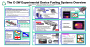
 The C-2W Experimental Device Fueling Systems Overview
Introduction
n The C-2W machine is the world’s premier Advanced Beam-Driven FRC
n Particle refueling is an essential component to attaining C-2W’s goal of long
enough (30 ms) and hot enough (3 keV) plasmas
n Meeting the varied particle inventory demands of this complex system requires several fueling options:
n Compact Toroid (CT) Injection (Core FRC fueling with warm deuterium plasma) n Pellet Injection (Core FRC and SOL fueling with cryogenic deuterium)
n Gas Puff (Edge fueling with deuterium gas)
Gas Injection / PI
n CTs injected from both East and West Devices
n Camera detects initial CT jets and fueling in core
n Interferometer detects traveling CTs and ultimate increase in density in core of FRC
CT Injection
Core Fueling
Pellet injector system is operational
Initial testing has been performed
Multiple pellets injected and seen by diagnostic camera
Dedicated fueling experiments planned
Gas Injection Sites
Machine Overview
Power Supply
Pellet Intersects FRC
n Two CT Injector systems operational on C-2W n Each system can produce up to 5 CTs per shot n Injected CTs have:
n 1 – 20 x 1018 particles
n Warm Ions and Electrons (~30-50 eV)
n Translation Velocity > 100 km/s (up to 200 km/s)
CT Injected at 500 μs
Typical Particle Loss Rate
n Density of FRC core and SOL must be maintained
n FRC density promotes beam capture
n SOL density required for edge biasing and reduces perpendicular transport
n Jet fueling required to maintain good electrical contact with divertor electrodes
Abstract
n Injector has 12 independently controllable barrels n Pellet velocity is ~ 0.5 – 1 km/s
n Each pellet has up to 1020 particles
n Six total gas injection piezo valves installed on C-2W n 4 valves in CV near ends
n 2 on each side N / S, 180 degrees apart
n 1 valve in each formation section near Outer Divertor
n Each valve supplies 2.5 x 10¹⁹ atoms / ms of puffing with 60 PSIA of back pressure for up to 30 ms
Pellet Injector
The experimental goals of the C-2W program are to demonstrate the ability to heat and maintain a field-reversed configuration (FRC) plasma to a total temperature of several keV for a period of 30 ms. As energy confinement times are improved, the particle loss rate will become the dominant limiter of plasma lifetime. In order to mitigate this loss channel several refueling methodologies have been implemented. They are: compact toroid injection (CTI), pellet injection, and gas puffing. Each of the two CTI systems is capable of injecting up to 5 CTs over the course of a single shot. The pellet injector launches cryogenically frozen pellets of deuterium from one end of the vessel, through the FRC’s X-point and into the core. By aiming the pellets such that they miss the beams, ablation of the pellets external to the FRC is minimized. Puff valves placed in strategic locations along the vessel add neutral gas to the scrape-off-layer (SOL). This keeps enough plasma outside of the FRC so good electrical connection with edge divertors is maintained. Each of the refueling methods can be used separately or in conjunction. Each provide a sufficient number of particles to overcome the particle loss rate. However, the regions of effective fueling varies between the systems.
Valve and Driver
Axial View of CV Valves
FRC
Radial View of CV Valves
CV Puffing Only
n Density of FRC core and SOL must be maintained
n FRC density promotes beam capture
n SOL density required for edge biasing and reduces perpendicular transport
Location
Confinement Vessel
Formation Section
Fueling Source
CT Injector Pellet Injector Gas Puff
GasPuff
Target
Core FRC Core FRC / SOL Jet / SOL
Jet
Rate
1019 / ms 1019 / ms 1020 / ms
6x10¹⁹ /ms
n Pellet injector fires cryogenically frozen slugs of D2 into near the end of C-2W confinement vessel
n
n n
n
§ FRC slowly decays during this shot.
§ Particle loss rate is lower when FRC is sustained § These values represent an upper bound for typical
loss rate
Formation Valve
n n n n
Injecting gas helps maintain connection to divertors
Shots with CV gas puff maintained mirror confined plasma longer than those without
Biasing current is maintained longer due to steady source of plasma from valves
Fine tuning of parameters to be performed in dedicated study
T. Roche, T. Matsumoto, I. Allfrey, D. Osin, M. Griswold, T. Hurn, L. Brown, K. Knapp, and The TAE Team
TAE Technologies, Inc., 19631 Pauling, Foothill Ranch, CA 92610 Schematic View
Gas Puffing Pellet Injector CT Injector
Initial Results Initial Results Initial Results
Electrodes
Bias Coil
FRC CORE
CT Injector arrangement on C-2W
Edge density increases as CT transits SOL Core density increases as CTs fuel FRC
| 1 |
