
Sokolov_APS_DPP_2019_V3
P. 1
Abstract
In TAE Technologies’ current experimental device, C-2W (also called “Norman”) [1], record breaking, advanced beam-driven field reversed configuration (FRC) plasmas [2] are produced and sustained in steady state utilizing variable energy neutral beams (15 – 40 keV, total power up to 20 MW), advanced divertors, end bias electrodes, and an active plasma control system. The end bias electrode system provides stabilization and heating of the high-beta axisymmetric plasmas by inducing azimuthal plasma rotation via the application of radial electric fields [3]. The radial electric fields are produced by flat coaxial bias electrodes and limiters, which are installed in the outer and inner divertors. The bias electrodes and limiters are designed for high voltage operation and were tested for up to 15 kV in vacuum. The bias voltage of -2 kV (on the device axis) with the total current through the electrodes of 5-7 kA were proven sufficient for stabilization of the C-2W plasmas.
[1] H. Gota et al., Nucl. Fusion 59, 112009 (2019).
[2] M.W. Binderbauer et al., AIP Conf. Proc. 1721, 030003 (2016). [3] A.D. Beklemishev et al., Fusion Sci.Technol. 57, N4, 351 (2010).
Biasing – stabilization mechanism
Biasing of electrodes – key method of plasma stabilization in mirror configuration and FRC
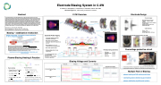
C-2W Overview
Electrode Design
• • •
•
Wobble (n=1) wall stabilization enhanced by plasma rotation
Small scale ballooning and interchange modes stabilized by differential rotation
Only fraction of biasing current converted into scrape-off layer (SOL) radial current. Reduction of distance between electrodes and FRC reduces lost current loops.
High initial gas pressure leads to high electrode current and arcing. For applying voltage to midplane, biasing has to overcome at least several Te ( > 5Te)
Requirements to electrode biasing system: high voltage design, good vacuum conditions
Plasma-Biasing Heating & Rotation
Plasma gun
•
Plasma Heating
•
o
o o o
ChargedParticleinF×,field
driftswithvelocity4 = G !#$% = *×,−./ −F
Ion acquires energy !"IJG J
>~! sothatLMOP " " LN
Ions with Larger rL can “feel” total ∆R
Electron Heating See M.Kaur UP10.00142
o Poloidalionvelocity 6 <(#">")
A
∆S
o Direction and velocity of rotation may differ for main and impurity ions (D",./")
• Radial E field See M.Nations UP10.00144
Courtesy – D. Osin
• Plasma Rotation
o Equationofmotionforions
South OD
South ID
North ID
North OD
AH &⃗ " "$'
123
45" = 7 89 : <@ − :B = 4$ + 4A &&; ;
Electrode Power Supply:
• Two power supplies for biasing electrodes, one per side.
• Both poles of power supplies electrically isolated from ground (up to 5 kV)
• Bias voltage up to +/– 3 kV, current up to 8 kA, duration 30ms
• Wave form operation mode
• Biasing configuration in those
experiments:
(-) in cental electrodes of OD (+) are grounded
Electrodes #3 are grounded Limiters are grounded
Electrode Biasing Voltage [kV]
Electrode Biasing Current [kA]
S. Outer Divertor
-10
S. Formation
Electrodes
S. Inner Divertor
Scrape-off layer
Confinement
NB injection
0 FRC Axial distance (m)
N. Inner Divertor
Separatrix 5
N. Formation
Magnets
N. Outer Divertor
North Outer Divertor
Working biasing parameters:
n Funnel limiter, OD electrodes and OD divertor of C-2W:
Overvoltage protective circuit
Courtesy – A.&S. Korepanov,V.Matvienko
n All electrodes and limiters are equipped with voltage and current measurement devices n All electrodes and limiters have individual over voltage and over spike protection circuit
Multiple Role of Biasing:
• plasma heating via ExB rotation and friction
• maintaining plasma density by gas ionization
• plasma stabilization by differential rotation
Electrode Biasing System in C-2W
V. Sokolov, S. Korepanov, P. Yushmanov, S. Putvinski, and the TAE Team TAE Technologies, Inc., 19631 Pauling, Foothill Ranch, CA 92610
1.5 1.0 0.5
0
-5
10
Biasing Voltage and Currents
North Inner Divertor
hg20180106.tae.1
Radius (m)
• OD bising
• Current per/side • Duration
1-3 kV 1-6 kA
30 ms 1-3 kV
•
ID biasing
Electrode Power Supply
CV
Onion skin design:
• Each electrode “sees” only two neighbors – scalable to higher voltages
• All biasable elements can be designed in same concept
• Separate biased electrodes with floating electrode(s)
C-2W divertors:
• Volume ~ 15 m3
• Cryo panels A ~ 20 m2
• Strong Ti gettering => ~2000 m3/s
| 1 |
