
APSDPP-2019_POSTER
P. 1
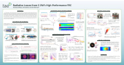
 Radiative Losses from C-2W’s High-Performance FRC
Timothy DeHaas, Ami DuBois, and the TAE Team
ABSTRACT
In TAE Technologies’ current experimental device, C2W (also called “Norman”) [1], record breaking, advanced beam-driven field reversed configuration (FRC) plasmas are produced and sustained in steady state utilizing variable energy neutral beams, expander divertors, end bias electrodes, and an active plasma control system. As energy confinement times and temperatures continue to improve, radiation and ionization losses due to impurities could lead to significant power loss. To monitor these losses, an array of over 600 channels of XUV and soft x-ray sensing diodes has been implemented. The diagnostic achieves both good spatial resolution and wide-angle collection of plasma emission. Additionally, the diagnostic is fitted with differing thin, metallic, optical filters for coarse spectral resolution. Multidimensional reconstruction of plasma emission is performed to infer the total power losses. In the C-2W’s high performance regime, which relies on extensive titanium gettering of the confinement vessel walls, the total impurity radiation power loss is estimated to be less than 200 kW. [1] H. Gota et al, Nucl. Fusion 59, 112009 (2019).
BOLOMETRY ON ‘NORMAN’
Diagnostic bolometry on C-2W is compact, modular, and inexpensive. There are over 600 channels, dispersed evenly over the confinement vessel. The system is designed to collect radiation and particle losses over wide ranges of solid angles and impact parameters. Four types of bolometers on C-2W are as follows:
ESTIMATING TOTAL RADIATED POWER
SPECTRAL RESOLUTION
     Axial Bolometer Array
We combine ALL detectors
Wide Collection Bolometers
Radial Bolometer Array
MODEL PROFILE OF FRC
Axial Array
Radial Profiles (shot = 116501)
No Filter
Al 750 nm
Mo 300 nm
Radial Array
One diode
uncovered
radiation and lost particles.
       We model the FRC as a ridged rotor with three region: the CORE, SOL, and Background:
! " ∝ $ %& ~ s e c h , - .
. = 2"&⁄23& − 1
$%
Sn 250 nm
Al 750 nm
Be 1000 nm
Mo 300 nm
Pd150nm
No Filter
Al 750 nm
Pd 150 nm
INSTABILITY ANALYSIS
OPTICAL FILTERS
The diagnostic has a series of five thin, modular, metallic, optical filters for coarse spectral resolution.
CORE SOL
We
power ∝ $%, a valid estimate confirmed by profile inversion
∝ $ %&
Max radiated power helps track progress
High-Performance Regime
Left: The Action, of the time integral of thermal energy, is used as a measurement of plasma performance. While low levels of radiation do not guarantee good performance, peak radiation above 300 kW is correlated with poor performance.
Clean-Up after vent
67
  BKG
 together to radiated power.
estimate
total
Knowing the distribution of radiation in the CV from $%& and the field of view of each detector, we use a linear least squares fit of the measurements to the etendue.
Abel Inverted Density Profile
Abel Inverted Radiation Profile (Al Filter)
per bolometer is left
  estimate the
radiated
to distinguish
between
&
  etendue
Overlapping lines of sight are fitted with multiple filters.
TEMPERATURE ESTIMATES
Thompson
Thompson
 ESTIMATES OF RADIATED POWER
    Axial Bolometer Array
x2 AXUVHS1 Distributed Axially
Designed for axial radiation profiles
Charge Exchange Bolometers
Fast Ion Direction
Using AXUVHS1 diodes, these diagnostics have wide collection and are angled for radiation and particles from > 30o
Radial Bolometer Array
Array Assembly AXUV20ELG
100 Narrow Chords which provide radial profiles of emission
Fast Ion Direction
SOL
ThreeShotComparisonofR &P s
With two sensors and at each position, we can provide for exploration of fast ion loss during instabilities
      CORE
     HIGH-PERFORMANCE REGIME
Wide Collection Bolometers
N
of view designed to see the majority of the plasma radiation from the FRC
MITIGATING RADIATIVE LOSSES
Losses are reduced and confinement improved through a combination of:
Experimental Techniques Effective Electrode Biasing Targeted Fueling Ti-Arc and Cryo Gettering
Ptot versus Plasma Performance poor performance
high performance
Right: Bolometry data may be used as a proxy for the wall conditions as the radiation is
Unfiltered
Radiation
Bolometer Estimates
         Tot
GrowthofPlasma Instability
Above: Band Passes at high energy provide a more time resolved estimates of electron temperature.
  110100
    114534
113389
 Wide View
Using AXUVHS1 diodes and pyrocrystals, these diagnostics have a wide field
S
Low levels are radiation are linked to high-performance shots.
An accurate estimate of the plasma center position is important to many estimates of physical plasma parameters and crucial to others, particularly if some type of profile inversion is necessary. Below: Shows the centroid of the plasma for an unusually unstable experimental.
Plasma Center
SUMMARY
• Bolometry on C-2W is highly modular and encompasses many goals in the understanding of FRC physics including: estimates of shape parameters, radiation spectra, impurity content, instability analysis, and fast ion loss.
• C2-W has continually decreased the amount of power lost which can be attributed to impurity radiation to < 100 kW, which is only 2% of the estimated losses in the confinement vessel.
• Due to the numerous number of channels, we can differentiate radiation coming from the core of the FRC, the SOL and the halo plasma.
CENTER OF EMISSION
       Stable Plasma for 30 ms
Low Levels of Radiation
Rs
Multiple intersection points between chords
    Electron temperatures 300 eV
The C-2W experimental program has achieved its goals:
Steady state plasmas for 30 ms duration with 3 keV total temperature.
Externally ramped magnetic pressure balanced by internally growing fast ion pressure (magnetic energy more than doubles over the 30 ms shot).
Fastionaccumulationasrecordedby neutronsignal(D+D➝ 3He + n)
Increasing Thermal Energy
Increasing Trapped Fast Ion Population
separatrix
x-point
O4+imageoftheFRCfromwithviewRight:inthex-yplane and Left: in the x-z plane
EFFECTIVE ELECTRODE BIASING
Biasing is vital for steady-state NB-driven C-2W plasma as it suppresses MHD and turbulent activity. In addition, effective biasing lowers radiative losses. Effective biasing may be estimated by measurements of impurity rotation in the CV.
∝89:;
TRANSIENT PERIOD
Multiple radial bolometer arrays are placed 90o apart for 2d reconstruction.
     EFFECTIVE BIASING
 Impurity Rotation
primarily
Through
cleaning, Ti and Cryo getting, performance is restored after a machine vent.
impurity effective
radiation. discharge
CX Neutrals
Continual improvement of Losses
Neutron Rate
Increasing time
EFFECTIVE BIASING
| 1 |
