
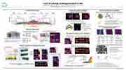
Radiative Losses from C-2W’s High-Performance FRC
P. 1
 1.5 1.0 0.5
Magnets
16
0
CV QCCG pressure from NB03
S. Outer Divertor
S. Formation
Electrodes
S. Inner Divertor
Conf nement
NB injection
N. Inner
Divertor N. Formation
N. Outer Divertor
Beam-into-gas shots validate NB model
0.4 0.3 0.2 0.1 0.0
• NB model accounts for grid size, divergence, duct loss
• R2 ∼ 0.7: residual due to reflections, divergence mismatch
Eb:5,7,9,11,13, 15
keV 3 2 1 0
H+ fast ions
6 8 10 12 14 Mono-energetic beam energy [keV]
Pyrobolometers2,3
• temperature change induces polarization current: Ip = γ P
• radial, co-, and counter-injection views
300
turning-point 200 10
Cρδ
• calibrated with pulsed blue light-source: 65 nA/W
Bragg wave- allow many
•
0.75 0.50 0.25 0.00
2.5 2.00
NBs on, 0.97ms nbi
midplane ne(r), Te(r), Ti(r)
3D neutral distribution for each source:
experimental image
2.00 1.75 1.50 1.25
2.5 1.00 2.0 0.75 1.5 0.50
0.25 1.0 0.00
0.5
0.0 optimize source magnitudes
3.5
radial camera image
neutral density slice
3210123 Z [m]
• Measured temperature change related to shot-averaged heat flux:
〈q⊥〉 = ρcpπrΔT/(2Δt)
• Sampled wall area is f(α, β)
Comparisons with simulated measure- ments are underway.
750 500 250
0 0.0
0.000
Te Ti
1.0 0.5 0.0 0.5 1.0
17
0.2
0.4 0.6 R [m]
0.8
2D plasma profiles 2D magnetic flux Φ(r, z)
101 17 17 0
f( , =0) f( = 0, )
0 20 40 60 80 Angle [deg]
42024 Z [m]
simulated diagnostic signals
0.50 1016 0.25
0.00
-10
-5
5 10 Plasma gun
High-speed, filtered cameras5,6
•
neutral sources:
NBI
NB gas bleed NB dump recycling wall recycling
degas2
Monte-Carlo neutral transport
0.05 0.04 0.03 0.02 0.01 0.00
sythetic diagnostics: pyrobolometer fiber-optic temperature sensor
camera geometry
compute synthetic camera
synthetic images:
7 6
54
3 2 1 0
0.5 0.4 0.3 0.2 0.1 0.0
3D neutral distribution
0.5 0.4 0.3 0.2 0.1 0.0
10 1016 1015
•
heating
Bragg gratings
camera
enclosure actuator
radial camera image
2.00 1.75 1.50 1.25 1.00 0.75 0.50 0.25 0.00
pyro-bolometer acceptance angles Lower simulated val- ues likely due to ther- mal ion CX not in- cluded in simulation
•
• distinct
deforms fiber
1.0 0.5 0.0 0.5 1.0
1017 1016 1015 1014
lengths
sensors per fiber
C-2W1 machine layout
TAE Technologies, Inc., 19631 Pauling, Foothill Ranch, CA 92610
Interpretive model validation
Fast-ion CX losses are acceptable
Monte-Carlo fast-ion modeling orbit-averages neutral density
Scrape-of layer
4
2
0
Radial view
0 FRC Axial distance (m)
10 1015
Instrument Overview
4 Fiber-optic temperature sensors
4 fibers
30 gratings ea. @ 15cm spacing
~0.3°C precision
neutralizer:
off, typ, high
co-inj
co-inj 6 4 2 0
DEGAS27 interpretive modeling framework
Without NBI: edge neutrals only
Distributed fiber-optic sensors have broad spatial coverage
20
15
10
5
Fast ion distribution CX and ion losses
Fast-ion 0.0 Monte Carlo
0.5 1.0
3
1017 0.4 0.2 0.0
1015
1014 0.4
0.2
0.4 0.6 R [m]
0.0
0.2
0.4 R [m]
0.6
[1] H. Gota et al. Nuclear Fusion 59.11 (June 2019), p. 112009.
[2] M. E. Griswold et al. Review of Scientific Instruments 89.10 (2018), 10J110.
[3] J Cooper. Journal of Scientific Instruments 39.9 (Sept. 1962), pp. 467–472.
[4] C. Massaroni, P. Saccomandi, and E. Schena. Journal of Functional Biomaterials 6.2 (2015), pp. 2014–221. [5] E. M. Granstedt et al. Review of Scientific Instruments 87.11 (Nov. 2016), p. 11D416.
[6] E. M. Granstedt, D. Fallah, and M. C. Thompson. Review of Scientific Instruments 89.10 (2018), 10E103.
[7] Daren Stotler and Charles Karney. en. Contributions to Plasma Physics 34.2-3 (1994), pp. 392–397.
1.0 0.5
1015
1016 0.0
1015
Axial view
Separatrix
0.0 0.2 0.4 0.6 0.8 R [m]
2
1
0
Z [m]
1
2
3
Fast-ion charge-exchange losses in C-2W
E.M. Granstedt, S.A. Dettrick, M.E. Griswold, D.K. Gupta, T. Roche, R.J. Smith, K. Zhai, and the TAE Team
sapphire window mirror adjustment
10x 2" dia filter wheel screw support end-cap
304SS mirror
• retracts during gettering
removable for cleaning
• spatially and radiometrically
calibrated
Radial view
Axial view
Reconstructed 3D neutral distributions
With NBI: CX capture of 15 kV NB → core neutral source
central
000 100 5
electronics
counter
0
re-entrant tube black anodizedwith lens motorized bellows
neutral density slice
3210123 Z [m]
location center center center axial t.p. axial t.p. axial t.p.
orientation counter-inj. radial co-inj. counter-inj. radial co-inj.
•
•
output integrated over
3.0 fit and residual images
Radial profiles and source contributions
2.0 1.75
RR
α
1.5 1.50
10
NBs off, 1.17ms 10 1016
dump bleed recy
10
1.0
1.25 0.5 1.00 0.0 0.75
r r
seff=s⊥=2r
seff=2r/cosα + O(r/R)
source magnitudes
10
14
0.2
• Primary edge neutral source: plasma and neutral wall recycling • Bump in neutral density at 0.2 m: NB impact parameter
61st Annual Meeting of the APS Division of Plasma Physics
Fort Lauderdale, Florida
HV off
HV on
cold gas bleed ≲ 1 torr-L/s
(5AH2)
•2AH attributedto15keV 2
0.05
0.10 Time [s]
0.15
metal surface
15 211
Gas bleed, dump recycling measured
beam → R
• consistent with particle
≲ 0.2 reflection from clean
dump
0.10 0.05 0.00
0.05 0.10
1017
2
1
counter
≈ 2.0 ms for fast ions from 15 kV H+ NBs • τcx ≳ 3.5 ms for confined population
• ∼3 kJ energy in fast ion population ⇒∼1.5 MW CX loss • ≲20% of ∼8 MW absorbed neutral power
• Dominant source of CX losses: neutrals from recycling Simulated loss distribution allows comparison with
pyro-bolometer measurement Fast ion CX (neutral) and direct (ion) losses
• τ
cx
1
21012 101 101
Z [m]
Pyrobolometer
= atan(vz/vr) [rad] simulation experiment
kW/m2 kW/m2 1 40–100
140 150–250 120 170–220 30 30–80 50 80–110
10 30–70
= atan(vz/vr) [rad] Simulation
particles
0.050
0.020
0.010
-0.001
0.005
0.002
0.001
R [m]
Effective H density [m 3]
recycling brightness [W/m2-sr]
dump brightness [W/m2-sr]
residual [W/m2-sr]
fit [W/m2-sr]
nHeff [m 3]
Pressure [ torr]
nHeff [m 3]
Brightness [W/m2/sr]
R [m]
Magnetic Flux [Wb]
bleed brightness [W/m2-sr]
NBI brightness [W/m2-sr]
particles
[kJ/m2] Aeff/A
Temperature [eV]
measured [W/m2-sr]
measured [W/m2-sr] R [m]
measured [W/m2-sr] R [m]
Effective H density [m 3]
Effective H density [m 3]
kW/m =
nHeff
[m ]
[rad]
23
atan(vt/vr) [rad] radial
Central PB
kW/m-rad
= atan(vt/vr) [rad]
Injected nfi [arb] Injected fast ion CX time [ms]
Turning point PB
kW/m-rad
radial
Radius (m)
hg20180106.tae.1
Residual [W/m2/sr], R2 = 0.70
| 1 |
