
APS-DPP_dkobayashi_v5
P. 1
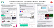
Behavior of a Tracer-Containing Compact Toroid in a Transverse Magnetic Field
D. Kobayashi1, T. Asai1, T. Seki1, R. Sasaki1, A. Minamigi1, H. Gota2, T. Roche2, T. Matsumoto2, T. Takahashi3, N. Tamura4, Y. Narushima4, and TAE team
1Nihon University, Tokyo 101-8308 Japan, 2TAE Technologies, Inc., Foothill Ranch, CA 92610, 3Gunma University, Kiryu, Gunma 371-8510 Japan, 4National Institute for Fusion Science, Toki, Gifu 509-5292, Japan
INTRODUCTION
The technique for injection an impurity ion-doped compact toroid (CT) has been proposed [1].
n It is called “Tracer-Containing Compact Toroid (TCCT)”
n TCCT can be used to inject impurity ions into magnetically confined plasmas
The TCCT is produced and accelerated by an MCPG with a tracer source injector.
n The tracer source is used to generate the plasma doped with impurity ions and supply it to an MCPG
n The generated plasmoid is accelerated up to about 100 km/s by an MCPG and it is ejected as a TCCT
The behavior of a TCCT in a transverse magnetic field has been observed by optical and magnetic measurements.
[1] D. Kobayashi, T. Asai, S. Yamada et al., Rev. Sci. Instrum. 89, 10I111 (2018).
MAGNETIZED COAXIAL PLASMA GUN
The MCPG consists of a set of coaxial cylindrical electrodes, bias coil and puff valves.
n The generated plasma is accelerated by Lorentz self-force (J B)
n The plasma captures the bias flux, and toroidal current is induced in it
n A compact toroid (CT) is ejected from an MCPG
n CT parameters
Magnetic profile of the ejected CTs
n Fueling to a field-reversed configuration (FRC) by CT injection
CT injection experiments had been successfully demonstrated on the C-2 series facility at TAE [2].
n Particle inventory of the FRC plasma was increased without disruption
Puff valve
Tracer source
(a) Schematic view of CT injector
(b) Cross sectional view of gas port
0 50 100mm
Outer electrode Inner electrode
Iron-core bias coil
(b)
(d)
(a)
(c)
Gas puff
Outer electrode
Inner electrode
Bias field
JGUN
BT
J ×B GUN T
ne [m-3]
Te [eV]
Velocity [km/s]
– 5×10²¹
– 30
– 100
Schematic view of the MCPG and CT ejection from an MCPG
Poloidal field
Toroidal field
Images of gas puff (left) and CT injection(right)
The time evolutions of the plasma radius and line-integrated electron density with CT injection at 0.5 and 3.0 ms
C-2U facility and CT injectors mounted on confinement vessel
[2] T. Asai, T. Matsumoto, T. Roche et al., Nucl. Fusion 57, 076018 (2017).
TRACER-CONTAINING COMPACT TOROID
The TCCT injection technique that utilizes an MCPG has been developed for injecting impurity ions into magnetically confined plasmas.
n Impurity ions are ejected with a magnetized plamoid
n The plasmoid is accelerated up to several tens to hundreds of km/s
TCCT
Bt
Impurity
Impurity Ion
Ion
BP
Wall
Fusion Plasma
Illustration of TCCT injection
Impurities
Plasma
PRELIMINARY EXPERIMENTS
n Can impurity ion-doped CTs be ejected?
n If ! ∗ # of each ion with different mass is same, each ion is accelerated by the same amplitude of Lorentz
self-force, therefore impurity ions should be separated from the CTs because these heavy.
n Metal ions derived from the inner electrode of an MCPG were accelerated without separation in each case [1]
n Why are impurity ions not separated from CTs?
n Larmor radius of singly ionized aluminum is bigger than radius of CTs (For B = 0.05 T, T = 10 eV)
n Momentum relaxation time should be short because the relative velocity of CTs and impurity ions is small when the initial stage of acceleration.
n CTs carry impurity ions by collision...?
Average velocity of CT and metal ions Larmor radius of each element for B = 0.05 T Momentum relaxation time of tungsten ion (W II) injected into deuterium plasma
TRACER SOURCE
The tracer source consists of a coaxially aligned rod electrode and a cylindrical electrode.
n The tracer source is mounted on the MCPG
n The rod electrode is the source of the CT dopants
n The tracer source is separately driven from the MCPG
n The inventory of doped impurity ions can be adjusted independently of CT parameters
Tracer source
MCPG
Rod electrode
3.3kV Max
Switch
0.4Ω
52μF
Schematic view of the tracer source and an MCPG with the tracer source
Typical waveform of current on the tracer source (t = 0 is discharge timing of the MCPG)
Schematic diagram of discharge circuit for the tracer source
n Spectra of the plasma generated by tracer source
The plasmas doped with impurity ions have been generated by using only the tracer source.
(a)
Discharge gas
Rod electrode
Charging voltage [kV]
Deuterium
Copper (φ 6.35 mm)
3.3
(b)
Cu I
Cu II
Spectra of (a) a CT and (b) the plasma generated by the tracer source
TCCT EJECTION
The velocity of impurity ions and a CT were measured using ToF method. In this case, copper is used as a tracer source.
Transverse field coil Btrans: 0.05 – 0.1 T
Fiber 2, 4 Fiber 1, 3
MCPG
Triple Langmuir probe
(a)
(b)
Typical waveform of electron density and PMT signals (a) with NDF, (b) with BPF (522 nm: Cu I). Velocity of the CT and copper ions were same ( – 60 km/s)
n Trajectory of TCCT
n Injected CTs and copper follow the almost
Glass tube
Fiber 5, 6, 7
Magnetic probe 1, 2, 3
100 mm
-2000
-1500 -1000 -500
0 [mm]
Experimental setup
n Copper ions are accelerated without separation from the CT
n TCCT has been successfully ejected by using the tracer source TCCT INJECTION INTO A TRANSVERSE FIELD
n Velocity of TCCT
n Magnetic probe signals and PMT signals of
CTs rose up coincidentally
n Magnetic probe signals of CTs and PMT signals of copper ions also rose up coincidentally
same trajectory
n Ejection of TCCT has been demonstrated with the newly developed tracer source n Behavior of TCCT in a transverse magnetic field has been investigated
n TCCT has been successfully injected into a transverse magnetic field n Trajectory of CTs and impurity ions are almost same
n We will investigate the behavior of TCCTs in detail
ACKNOWLEDGMENT
The authors would like to acknowledge all of the Nihon University teachers and TAE staff who contributed to this experiments and discussions. This work was partially supported by JSPS KAKENHI Grant Number 19K21868, 16K06939, JSPS Overseas Challenge Program for Young Researchers and Grants-in-Aid of College of Science and Technology, Nihon University.
n Impurity ions travel with CTs
(a)
(c)
MCPG
(b)
Images of injected TCCTs taken by iPhone
(a) with BPF (656 nm: Dα),
(b) with BPF (522 nm: Cu I),
(c) without BPF
Typical magnetic probe and PMT signals
n Impurity ions and a CT have been successfully injected as a TCCT
SUMMARY
Transverse field coil
| 1 |
