
Page 2 - Jet outflow and open field line measurements on the C-2W advanced beam-driven field-reversed configuration plasma experiment
P. 2
10D120-2
Sheftman et al.
Rev. Sci. Instrum. 89, 10D120 (2018)
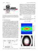
FIG. 1. Overview of C-2W inner divertor (left) and confinement (right) sec- tions and diagnostics to be installed (figure not to scale). The narrow section between the divertor and confinement is the mirror section. The formation section is on the far left. The machine is symmetric around the FRC location in the figure.
B. Divertor interferometer
A multi-chord, monostatic, homodyne microwave (MW)
interferometer was developed to measure the electron density
in the inner divertor. This 5 chord system consists of modules
placed on a vibration isolated mechanical breadboard at the
top of the inner divertor. The chords are arranged in 10 cm
spacing to measure the radial profile of the electron density.
Each chord includes a chain of synthesizer at ∼12.75 GHz,
6 × multiplier, bypass mixer, and 20 dB horn antenna. The
bypass mixer uses a portion of the outgoing signal and mixes it
with the reflected signal that goes through the plasma to obtain
I-Q detection (see Fig. 2). This system was designed and built
by ELVA-1 and is similar to a system used at the Moscow
5
using bellows and is thus effectively isolated from machine vibrations (see Fig. 1). The reflector has a focal length of 3.6 m on the short side, enabling the beams to pass clear through a 1.25 m long, 20 cm wide entrance window at the top of the divertor. Simulations of the MW beam propagation were performed using CodeV software. The elliptical shape of the beam at the return path can be seen in Fig. 3. In that figure, the intensity and fringe profile are presented at the loca- tion of the horn. It can be seen that sufficient contrast of the MW interference pattern can be obtained. Each two adjacent chords are shifted with respect to each other by 250 MHz in operational frequency, in order to ensure that adjacent signals are filtered out from each chord. The phase ∆φ of the prob- ing beam is extracted from the quadrature phase detection as follows:
I(t) = C1 + A cos(φ0 + ∆φ(t)), Q(t) = C2 + B sin(φ0 + ∆φ(t)),
(1)
Institute of Physics and Technology.
76-77 GHz, completes a double pass through the plasma for a total path length of ∼8.5 m. Such a large path length can be extremely challenging for interferometry, and optical design is required to keep the MW beam sufficiently small. Each chord includes a 20 cm focal length HDPE lens. A 20 cm wide, 1.2 m long cylindrically curved reflector placed inside the divertor vessel returns the beams back to the modules. The reflector is placed on a support structure which is mounted to the con- crete floor and accessed through vacuum ports on the machine
where C1, C2, A, and B are obtained from calibration. The integrated electron density is then calculated as
∆φ
nedl = 4πc2mε0 λe2 , (2)
FIG. 3. CodeV simulation of the reflected MW beam profile at the horn location: (a) relative power and (b) fringe pattern.
The outgoing beam, at
FIG.2. SchemeofanindividualchordofthedivertorMWinterferometer.
