
First time-resolved electron density measurements in the C-2W advanced field-reversed configuration plasmas from long-path compact second-harmonic interferometer
P. 1
Both dispersion interferometers consist of a pair of optical units using two second harmonic generation (SHG) crystals to generate a two-color collinear single-chord line-integrated density measurement, with a general optical schematic shown in Fig. 2.
The laser is a fiber-coupled 1064 nm Nd:YAG (MEPHISTO and Innolight) with power up to 1.2 W. The near- infrared (NIR) fundamental wavelength and visible second
Note: Paper published as part of the Proceedings of the 22nd Topical Confer- ence on High-Temperature Plasma Diagnostics, San Diego, California, April 2018.
a) Author to whom correspondence should be addressed: mbeall@tae.com. b)TAE Team members are listed in Nucl. Fusion 57, 116021 (2017).
∆φ = 4π λL
nλ(z) − nλ/2(z)dz, (1)
REVIEW OF SCIENTIFIC INSTRUMENTS 89, 10B113 (2018)
First time-resolved electron density measurements in the C-2W advanced field-reversed configuration plasmas from long-path compact second-harmonic interferometer
M. Beall,a) D. Sheftman, and TAE Teamb)
TAE Technologies, Inc., 19631 Pauling, Foothill Ranch, California 92610, USA
(Presented 17 April 2018; received 23 April 2018; accepted 19 June 2018; published online 12 October 2018)
Characterization of the plasma structure and density is critical for the diagnosis and control of C-2W plasma equilibria. To this end, two compact, highly portable, turnkey second harmonic interferometers are used to make measurements with greater flexibility than available from other diagnostics, providing important information in areas otherwise inaccessible to more complicated systems. The systems are based on a fiber-coupled 1064 nm Nd:YAG laser and provide a sensitivity of a few 1018 m−2 with a time resolution of a few microseconds. System upgrades were made to allow for beam paths in excess of 5 m. Initial data from two system configurations are presented, showing plasma translation and merged equilibria. Published by AIP Publishing. https://doi.org/10.1063/1.5037329
I. INTRODUCTION
TAE Technologies’ C-2W experiment1 is intended to
demonstrate confinement scaling of advanced beam-driven
field-reversed configuration (FRC) plasmas using new heat-
ing, refueling, pumping, and magnetic control systems. Given
the complexities of these techniques, it is necessary to couple
2
harmonic avoid a number of technical issues associated with a carbon dioxide laser and are additionally well suited for several other secondary experiments, particularly formation ionization tests. The fiber is routed from electromagnetic interference (EMI) shielded screen rooms to a pair of small sheet-metal boxes mounted to vacuum flanges on opposite sides of the vacuum vessel. In the first box, the laser passes through a BiB3O6 crystal, partially converting it into 532 nm green light. Both the lasers then pass through a 532 nm half wave plate, which rotates the green light by 90◦ without modifying the NIR. A BK7 window with antireflection coating attached to a motorized mirror mount serves to compensate for spurious dis- persion. The two beams then pass through the plasma, picking up wavelength dependent phase changes. In the second opti- cal unit, a small fraction of the rest of the NIR is converted to 532 nm, and a pair of filters cuts out the remaining NIR power and any stray light from the plasma. The green light from both the SHGs enters a polarizing beam splitter set at 45◦ to the axis of the SHGs, producing transmitted and reflected beams with interference patterns shifted by π which then travel by fiber back to the source room for detection and digitization. Detec- tion is performed by using FEMTO OE-200-SI variable gain photo-receivers, providing a time resolution of a 100 kHz, and digitized by D-TACQ ACQ424ELF units at 1 megasample per second. In order to facilitate alignment, all the components are mounted on a standard optical cage, supported by a kinematic mount. The expected phase difference from the plasma is3
them with a very large suite of diagnostics tools.
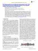
the interests of rapid innovation, it is not desirable to postpone all operations until some of the more sophisticated instruments are available, and even when installed, few diagnostics are capable of surveying the entire machine geometry, which is shown in Fig. 1. To this end, a pair of highly portable disper- sion interferometers3 is employed in multiple configurations around the vacuum vessel in order to provide density informa- tion at critical locations for different phases of development and research. In Sec. II, the diagnostic design and configura- tion are described. In Sec. III, some initial experimental data are shown, demonstrating the applications of the system. In Sec. IV, known system issues are described, and some solu- tions are presented as future work in Sec. V. The paper is summarized in Sec. VI.
II. DIAGNOSTIC OVERVIEW
However, in
0034-6748/2018/89(10)/10B113/5/$30.00 89, 10B113-1
Published by AIP Publishing.
FIG. 1.
Layout overview of the C-2W device geometry.
