
Page 3 - Thomson scattering systems on C-2W field-reversed configuration plasma experiment
P. 3
Zhai et al.
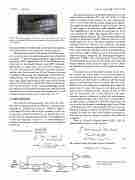
FIG.3. Thebrightrectanglesonthesurfaceofmetalbararethebackprojected image of fiber bundle. The honeycomb structure on top of the projected view is view dump.
beam is performed with Rayleigh scattering by fine adjusting
15
Polychromators built in collaboration with General Atom-
ics are used to resolve the spectrum and intensity of scattered
15,16
Rev. Sci. Instrum. 89, 10C118 (2018) In each polychromator wavelength channel, there are two
16
10C118-3
the collection optics to maximize the scattering signal.
laser light.
expected C-2W Te range from 10 eV to 2 keV. Each polychro- mator has five wavelength channels using APD (Avalanche Photodiode) as a light sensor. One of the five channels is at the laser wavelength for the Rayleigh scattering experiment, and the other four channels are for the Thomson scattering experiment with passing wavelength bands of 850-1005 nm, 1005-1039 nm, 1039-1055 nm, and 1055-1061 nm. An inte- grator gate signal monitoring port has been installed on the control unit front panel to adjust the timing to synchronize the 40 ns gate with the ∼10 ns scattering pulse signal. All the polychromators are installed in a temperature-controlled room about 20 m away from the machine. Polychromators are stored in closed cabinets and are water cooled at 20 ± 0.1 ◦C.
Pts(λs)nePiLdλsdΩ =
√
plasma
The wavelength channels are optimized for the
III. DATA ANALYSIS
The total laser scattering energy collected by the collec- tion optics is determined by the Thomson scattering power spectrum Pts, incident laser power Pi, collection length L, solid angle dΩ of the collection lens extending to the scat- tering region, and electron density ne, as shown in Eq. (1),13 in which a is the electron thermal velocity, c is the light speed, θ is the scattering angle, and ∆λ = λs − λi is the difference of scattering wavelength λs and the incident laser wavelength λi at 1064 nm,
To analyze the scattering light spectrum and its abso- lute intensity, the system needs to be calibrated. Details of the system calibration are discussed elsewhere in Ref. 15. In general, there are three types of calibration with this unique design of polychromator detection system. The first one is APD detector unit calibration, in which the gain of the DC output and AC output with respect to the input power and pulse energy is calibrated as RDC and RAC in units of V/W and V/J, respectively. The second calibration is the poly- chromator spectral calibration, in which the polychromator spectral channel response R(λ) with respect to polychroma- tor input energy is calibrated at each wavelength with 1 nm step over the polychromator wavelength range from 850 nm to 1070 nm in unit of V/J. The final calibration uses argon gas Rayleigh scattering to calibrate the absolute system intensity response, in which the slope of the Rayleigh scattering sig- nal versus the argon gas pressure determines the calibration coefficient.
With the schematics diagram shown in Fig. 4, the AC channel output SignalAC can be written as
Pi ro2 ne Lcd Ω
Tgate 0
P (t)+P (t)−P t+T
delay
output channels marked as “DC” and “AC” in Fig. 4. feature is designed to help separate the laser scattering sig- nal of ∼10 ns width from the plasma background radiation. The signal after the preamplifier is split into three. One of the split signals is fed through a buffer amplifier which is then sampled/held at 200 ns after the laser pulse for 20 μs and is digitized at 1 MHz. This digitized DC output is for background plasma radiation. The other two split signals pass through an operational amplifier subtractor with one of the signals delayed by 40 ns. The plasma radiation is assumed unchanged in 40 ns; therefore, after subtraction, the signal only contains the scattering signal shown as two inverted peaks with ∼10 ns width and separated by 40 ns. A synchronization gate of 40 ns width is applied to one of the peaks, during which the signal is integrated. The final integrated signal is digitized at 1 MHz as the scattering signal. One advantage of separating the laser scattering signal from the background plasma radiation is that these two signals can have differ- ent amplification and make full use of the digitizer dynamic range.
ts
− Pplasma
ts t + Tdelay dt
This
z
π sin(θ/2)λi 7 ∆ λ
×1−+
23
= Sts + Splasma − Splasma = Sts .
The variance of the AC channel signal is therefore
VarianceAC =Vts +2Vplasma.
(2)
(3)
2λi 4a λ sin(θ/2) i
c2(∆λ)2
× exp−
i
dλs. (1)
c 2 ( ∆ λ ) 3
4a2λ2 sin(θ/2)
FIG.4. SchematicdiagramoftheAPD and preamplifier unit.
