
Page 4 - Thomson scattering systems on C-2W field-reversed configuration plasma experiment
P. 4
10C118-4 Zhai et al.
Rev. Sci. Instrum. 89, 10C118 (2018)
The laser scattered signal Sts can be written as Cgain∗Ne-photon, in which Ne-photon is the number of photon-electrons after APD conversion and Cgain is the gain of APD and the following circuit combined together. Sts variance is then Vts = Fnoise∗Cgain∗Ne-photon, in which Fnoise is the enhanced APD noise factor due to the nature of the random process of APD avalanche amplification. The APD used in the polychro- mator detection system is C30956EH from Excelitas, and its noise enhancement factor is ∼4.9 from the vendor’s datasheet. The quantum efficiency of APD is QAPD(λ), and the num- ber of photon-electrons in each polychromator channel can be rewritten as Ne-photon = QAPD∗Nphoton, in which Nphoton is the scattered photon number collected in the individual poly- chromator wavelength channel. For simplicity, the value of quantum efficiency QAPD is taken at the center wavelength for each polychromator wavelength channel. The polychro- mator has 5 wavelength channels that center at 929.68 nm, 1021.22 nm, 1046.53 nm, 1057.83 nm, and 1064.42 nm, and the corresponding QAPD used in the data process is 0.84, 0.56, 0.40, 0.34, and 0.30, respectively. The scattered photon number Nphoton can be calculated from the scattered power spectrum as described in Eq. (1) as
Nphoton = Pts(λs)∗E∗∆λs ∗∆Ω∗L∗Ne ∗Fsystem ∗T(λs), s hc
in which T(λs) is the transmission coefficient that con-
verts the power at the polychromator input to the power
that hit on the APD reception surface. It is straight forward
that T(λs), R(λs), QAPD(λs), and Cgain are related with the
following equation: R(λ)=T(λ)∗Q (λ)∗C /(hc/λ). apd gain
With some reorganization and including the Rayleigh scattering calibration coefficient Cray, the scattering sig- nal and its variance in the polychromator AC channel are
Sts = Pts(λs)R(λs) Ne ∗ ∆λs ∗ Cray (5) i RRay−ch(λi) ∗ dσray
λs
(4)
and
V = (P (λ)R(λ))R(λ) i F
λ
ts tss s s i
noise T(λs)Qapd
dΩ hc
Ne ∗ ∆λs ∗ Cray
× dσ . (6)
RRay−ch(λi) ray dΩ
From Fig. 4, the background plasma radiation power Pplasma can be obtained from the DC channel output SDC and the calibrated DC channel response RDC as Pplasma = SDC /RDC . The gate width Tgate is 40 ns in our experiment; the equivalent plasma radiation energy in the AC channel dur- ing the gate period is Pplasma∗Tgate, which can be con- verted to the equivalent photoelectron number from plasma radiation
Ne−photon−plasma =(Pplasma ∗Tgate ∗QAPD)/(hc/λs−center), (7)
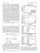
FIG. 5. Data processing for shot 104709 at r = −5 cm. (a) Integrated raw signal in each polychromator channel. (b) Signal from the DC out- put in each polychromator channel, representing background plasma radi- ation. (c) Total likelihood for different test Te; the inset shows Te with maximum likelihood and its 1-σ error bar. (d) Total likelihood for differ- ent test ne; the inset shows ne with maximum likelihood and its 1-σ error bar.
