
Page 4 - Anatomy of a field-reversed configuration
P. 4
Physics of Plasmas ARTICLE
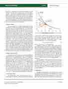
FIG. 2. Profile of P0(w) for various ac.
by requiring the P(w) to be continuous at w 1⁄4 0 through the second 00 5
where ‘i 1⁄4 (mi/l0q2nmax)1/2 is the ion skin depth.
Consider the question of a “realistic” rotation rate X. The pur-
pose of edge-biasing in modern FRCs is to reduce the rotation of the thermal ions and thereby suppress rotational instability. Stopping ther- mal ion rotation in typical experiments requires voltages comparable to the thermal ion temperature (a few hundred eV). Fast ions supplied by neutral-beam injection have much higher energy and thus a rota- tion rate Xfast proportionately higher. Thus, edge biasing only mod- estly reduces Xfast. However, fast ions account for a relatively small fraction of the density; thus, the average rotation, accounting for both fast and thermal ions, is much less than Xfast. The discussion in Appendix C addresses this in some detail, finding that X/XJ 1 is a realistic value.
The centrifugal effect shifts the pressure peak outward and causes the separatrix pressure ps to exceed the axis pressure p0 by a factor
2
5. Algorithm
The algorithm of Grushenka has the following steps. (1) Data {ww(z,t), R/(z,t)} are collected from an experimental shot. (2) The data are distilled to extract a smooth fit ww,fit(z) and {R/,Z/}. (3) A nested algorithm iterates both w(r,z) and the parameters {Ps, ac} until conver- gence to the target values {R/,Z/}, at the same time converging w(r,z)
27, 112508-4
derivative P (w). Details are presented in Appendix B. The adjustable parameters are {Ps, ac}: Ps is a multiplicative factor while ac mainly affects the shape of P(w) in the core (w < 0). Figure 2 shows a family of profiles for the derivative P0(w) jh/r. The various curves have dif- ferent values of ac/wR, where wR BwR/2/8 is a reference flux (recall Bw is the wall field at the mid plane). The curves “þ1” and “þ0.5” have peaked current profile because P0(w) rises inward from the sepa- ratrix. The one marked “0” has a flat current profile. The ones marked “0.5” and “1” have hollow current profiles because P0 falls inward.
exp(GR/
4. Centrifugal effect
The centrifugal effect appears as an exponent factor in Eq. (5), exp(Gr2) where G 1⁄4 miX2/2kTtot. This allows the freedom to prescribe
Phys. Plasmas 27, 112508 (2020); doi: 10.1063/5.0022663 Published under license by AIP Publishing
G 1⁄4 ð2:4‘i=R2/Þ2ðX=XJÞ2;
(6)
). For a typical case with Bw 1⁄4 0.09 T, R/ 1⁄4 0.4 m, and a deu- teron plasma with nmax 1⁄4 1.5 1019 m3, the separatrix-to-axis pres- sure ratio is ps/p0 1⁄4 1.28. In results that follow, two cases will be considered: (a) the non-rotating case X 1⁄4 0, given the long history of Grad–Shafranov solutions, and (b) the rotating case relevant to mod- ern FRCs with X/XJ 1⁄4 1.
scitation.org/journal/php
Here, P(w) is a surface function, X is the rotation frequency, mi is the ion mass, k is the Boltzmann’s constant, and Ttot is the total tempera- ture (ions þ electrons). For simplicity, both X and Ttot are approxi- mated as constant. The prime attached to P denotes the derivative of the function with respect to w. The exponential factor is the centrifugal effect, the same as appears in the pressure p 1⁄4 P(w)exp(miXr2/2kTtot). A suitable form of P0(w) will be described shortly. Note that Eq. (5) does not indicate explicitly how the current is distributed between elec- trons and ions (thermal and fast). The rotation frequency X affects the various contributions as will be discussed shortly.
2. Kinetic effects
The current density, Eq. (5), builds on a fluid model, which can be criticized in the FRC context because of relatively large ion orbits, both in the core for all ions and everywhere for a fast-ion population created by neutral-beam injection. Even so, the form in Eq. (5) can accommodate four kinetic effects. (1) End loss is a kinetic effect that steepens the fall of P(w) in the SOL (w > 0). The P(w) function adopted shortly employs different forms in core and periphery to reflect this. (2) Centrifugal effects, another manifestation of kinetics, elevate the current density on the outboard side of a closed flux surface compared to the inboard side. (3) Rigid-rotor kinetics: the P(w) func- tion is built up of components of the fully kinetic rigid-rotor construct of form P(w) exp(const w). (4) Finite-Larmor smoothing of the P(w) profile is accommodated by forcing a smooth core-to-periphery transition. A kinetic effect not accounted for is thermal anisotropy of the fast ion population created by neutral beam injection giving rise to different orbit types (drift, betatron, etc.). Including these would require a more sophisticated physics construct beyond the scope of the present model. Suffice it to say, any practical model of the current den- sity is of necessity an imperfect artifice, and the present model is no exception. It should be noted that an equilibrium model with a fully kinetic treatment of the ion population5 exhibited properties remark- ably similar to those of static plasma (Grad–Shafranov) equilibria.
3. Shape of P(w) function
The surface function P(w) must have two-parameter flexibility to
accommodate the pair of shape dimensions {R/, Z/}. The adopted for-
mat for P is the “composite rigid-rotor,” a linear sum of rigid-rotor
like components on each side of the separatrix. In addition, a “filet”
contribution is added to enforce a smooth transition from core to SOL
a realistic rotation rate X. It is useful to express X as a fraction of a ref- erence rotation rate, the “current” drift XJ 1⁄4 jh/rqn 1⁄4 j$ptotj/qBnir (q 1⁄4 ion charge). A reasonable expression for XJ is as follows. In the quasi-1D approximation XJ 1⁄4 8jkTpb/qBwRs2, where j is a shape factor with typical value j 0.6. Combining these yields
