
Page 1 - Tobin-APS-DPP-2020-poster
P. 1
•
• • • •
•
•
Toroidal Mode Number Toroidal Mode Number N=2 N=1
• Columns of +? are normalized, linearly independent, and describe the mode shapes in the @ dimension; Σ indicates mode strengths; all real-valued tensors
N4
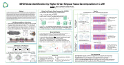
MHD Mode Identification by Higher Order Singular Value Decomposition in C-2W
Abstract
The C-2W device (also known as ‘Norman’) at TAE Technologies has proven successful at generating stable, long- lived field-reversed configuration plasmas (FRCs) with record temperatures [1]. Detection of magnetohydrodynamic (MHD) mode structures in these plasmas is crucial to understanding and predicting plasma instability and the conditions that give rise to it. MHD mode structures, when they do appear, cause fluctuations in the magnetic field within and surrounding the plasma, which can be detected by magnetic field sensors such as Mirnov probes. The largest Mirnov probe array in C-2W, consisting of 64 probes, is roughly rectangular, that is, evenly spaced in two dimensions [2], which creates a unique opportunity to apply higher order singular value decomposition (HOSVD) [3] to efficiently analyze the external magnetic field data recorded by these probes for the purposes of reconstructing the MHD mode structures in the FRC. This versatile method is shown to quickly and effectively detect and separate toroidal modes while indicating longitudinal dependence of mode phases, enhancing the coherence and utility of the vast quantity of data produced by this array.
M. Tobin, T. Roche, T. Matsumoto, and the TAE Team
TAE Technologies, Inc., 19631 Pauling, Foothill Ranch, CA 92610 Higher Order Singular Value Decomposition (HOSVD)
Results
Analyses based on !" and +" except where noted otherwise
• SVD generalizes eigen decomposition to non-square matrices:
, = .ΣU1
is a 2D data matrix (time x space)
. ∈ R4×4; + ∈ R6×6; Σ ∈ R4×6 is a diagonal matrix of singular values
• HOSVD extends this to third (and higher) order tensors [3] ,=Σ× + × + × + (...)
Mode Shape Vectors
Mode Phase Plots:
4×6 , ∈ R
!" analysis:
!# analysis:
!" analysis:
- -
-
From +":
2 zero-crossingsèN = 1 Mode vectors 90° out of phase
From +M:
!" is odd; !M is evenàWobble
From +":
- 4 zero-crossingsèN = 2
- Mode vectors 45° out of phase
• Apply to 3D Mirnov array dataset (> x * x time) +#
x
+ABCD
+ 8899:: "
- -
- - -
-
! : All North rings in phase, "
180° out of phase with South
Agrees with odd mode vector in +#
! : Rings in phase across #
midplane
180° phase shift at FRC axial boundary
Agrees with even mode vector in +#
!": All North rings approximately in phase; 180° out of phase with South
!" and !# : North and South rings in phase; no phase shift at FRC axial boundary
Can be used to determine if FRC is present
Consistent with kink instability
C-2W Device and Mirnov Probe Array
Field-reversed configuration plasmas are compact tori with low toroidal
field and poloidally closed magnetic field lines within a ‘separatrix’ [5]
C-2W FRCs are long-lived (~30 ms) and hot (QDRB ~1.2—3.0 keV) [1]
MHD modes stabilized by plasma guns, end biasing, FLR effects [6, 7]
̇̇̇
8 rings of 8 Mirnov probes each, which measure !U, !", and !# [2]
Symmetric about midplane; rings ~ 50 cm apart, probes ~ 45° apart
>,x *
Σ
x
• + : toroidal mode shapes, + : longitudinal mode shapes, +
" # ABCD
Mode Identification
: time evolution
S4
Diverters
S3
S2
S1
N1 N2 N3
Cross section:
θ
R Z
Neutral beams
Mirnov probe:
Formation sections
Cutaway of the C-2W device
Mode Phase Plots: !# analysis:
Confinement vessel
• 8 azimuthally spaced probes à resolve up to toroidal mode number N = 4
• Periodic oscillations in !" (and !#) signals when mode present
• Plasma symmetry across midplaneàantisymmetry in !", symmetry in !# [4]
• 2 vectors with a phase difference of $%° are needed to describe each rotating '
mode in the ( − * plane (since all tensors are real-valued)
• Zero-crossings in toroidal mode vector = 2 x toroidal mode number
• Analyzed in 500 μs-long windows; FFT used to extract mode frequencies
• Mode shapes are global; magnitudes and frequencies evaluated at each ring
!" analysis:
MHD Modes in FRC Plasmas
Bulk plasma rotationàglobal macro-instabilities: EF=∇× H×F% ; H=IKJ=displacement
E!"=L I!M −L −I!N ;E!M=−L(I!M) LMLN L"
+"
Two vectors in +" matrix sum to describe each rotating mode
=
-
- -
For FRC: !M −O = !M O ,!N −O = −!N(O)
Can degrade confinement or lead to catastrophic collapse of FRC [4]
Mode magnitude evaluated at each ring
(External) Tilt:
I −O = −I O E!" O =E!"(O)
E!M −O =−E!M(O)
Wobble:
I −O = I O E!" −O = −E!" O E!M −O = E!M(O)
References
• • • • • •
Key Conclusions
First application of HOSVD for MHD mode identification using magnetic field measurements
First application of SVD for this purpose in FRCs (previously applied in tokamaks [8, 9, 10]) Fourier decomposition assumes the basis vector shapes; SVD uses an eigen basis
HOSVD is computationally more efficient, as all 64 Mirnov probes can be analyzed simultaneously Global modes better identified on rings with weaker signals when all rings are analyzed together Allows clear observation of N = 1 phase shift of 180° at FRC axial boundary
Vessel Wall
Axis of Rotation
[1] H. Gota et al., Nucl. Fusion, 59, 112009 (2019).
[2] T. Roche et al., Rev. Sci. Inst., 89, 10J107 (2018).
[3] L. De Lathauwer et al., SIAM J. Matrix Anal. Appl. 21,
1253-1278 (2000).
[4] Y. A. Omelchenko et al., Phys. Plasmas 8, 4463 (2001). [5] M. Tuszewski et al., Nucl. Fusion, 28, 2033 (1988).
[6] M. Tuszewski et al., Phys. Rev. Lett., 108, 255008
(2012).
[7] L. Schmitz et al., Nat. Commun., 7, 13860 (2016). [8] C. Nardone, Plasma Phys. Control. Fusion, 34, 1447
(1992).
[9] J. S. Kim et al., Plasma Phys. Control. Fusion, 41, 1399
(1999).
[10] M. J. Hole and L. C. Appel, Plasma Phys. Control.
Fusion, 49, 1971 (2007).
Mirror Plasma N = 1 N = 2 N = 1 Wobble mode (shot 116998) (shot 120599) (shot 119839)
time
| 1 |
