
Page 1 - ZHAI-APS-DPP-2020-poster_final
P. 1
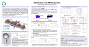
 Rigid motion of C-2W FRC plasma
K. Zhai, E. Parke, J. Sweeney, M. Beall, J. Kinley, M. Kaur, and the TAE Team
TAE Technologies, Inc., 19631 Pauling, Foothill Ranch, CA 92610
      Abstract
C-2W is an advanced beam driven Field Reversed Configuration (FRC) fusion device [1], in which plasma sustainment with total temperature at 3keV has been demonstrated. The DC output channels of the C-2W Thomson scattering (TS) polychromators, which are designed for system spectral response calibration and to monitor background plasma radiation for measurement uncertainty analysis, can be used to characterize the plasma motion. Due to the nature of an imaging system designed for TS collection optics, the background radiation recorded in the DC channels of the sixteen polychromators are mainly from the sixteen fixed spatial locations where the TS measurement is designed at. The time evolution of the signals from different polychromators form a unique pattern determined by FRC rigid plasma motion. Detailed analysis and its comparison with the FIR interferometer measurement is presented.
[1] H. Gota et al., Nucl. Fusion 59, 112009 (2019).
C-2W is an advanced beam driven FRC fusion experiment
  Formation section (both sides)
Eight neutral beams, ~21 MW, ~30 ms
Inner divertor (both sides)
Outer divertor with plasma gun and biasing electrodes (both sides)
   Parameter Bext
rs
Ls
ne Ttot=Te+Ti Pulse length
 Value
~ 0.1–0.3 T
~ 40 cm 2-3 m (1–3)×1019 m-3 up to 3keV up to 30 ms
Central confinement vessel
  C-2W Thomson Scattering system can measure plasma background radiation
   TS system setup
bremsstralung emission.
Five-channel polychromator
1. Collection optics image 16 locations along the laser beam path onto corresponding fiber bundles, r= [-8, -4, 0, 4, 8, 12, 16, 20, 24, 28, 32, 36, 41.25, 49.25, 57.25, 65.25] cm
2. Each fiber bundle feeds into a corresponding polychromator.
3. Each polychromator has five spectral channels, each channel splits the signal into AC and DC signals. AC output is for the Thomson scattering measurement, and DC output is for the background radiation measurement which is mainly plasma
Each APD channel splits the signal into AC and DC output
  Diagnostics model and simulation results
1. Plasma bremsstrahlung radiation ~ !"# %&'( *(,, . ) $)" /
"
2. In the wavelength range of 850-1000nm and Te ~ 300eV , terms of g and % )"
so plasma bremsstralung radiation is mainly determined by 1/.
3. When plasma moves as a rigid object, each detection channel senses different part of the rigid plasma body. This forms a unique pattern of the detected signal. Assuming plasma body is azimuthally symmetric, the pattern is determined by the distance from the measurement location to the center of plasma body.
&'(
are almost unity,
  impact distance,
trajectory angle
Rigid translation
4. For different shapes of plasma density profile, the signal evolution in each detection channel can be obtained from the motion of the plasma body.
These two peaks are due to the peak density passing the measurement location
1) Distinctively different patterns between plasma rotation and translation. 2) Plasma rotation case:
• A feature of two peaks spreading out in the rotation pattern is due to the peak density passing around measurement location. The starting point when the single peak splits into two spreading peaks is determined by Rs and radial FRC center shift.
• The reoccurring period determines rotation frequency. 3) Plasma translation case:
• The motion impact distance and direction determine the shape evolution at different measurement locations. Plasma translational motion speed can be estimated from different time of the peak signals at different measurement locations.
5. Following the same rules, the expected integrated line density from each FIR chord can be simulated.
Rotation frequency and translation speed can also be obtained from the signal pattern, which is complementary to the results from the Thomson scattering DC channels measurement.
     Plasma center trail
Rigid rotation
Peak density location
16 measurement location
                 An example of C-2W plasma rigid motion: shot 119223
      Summary of shot 119223
Signal from 16 polychromators spectral-1 DC channels
   Plasma rotation at 10 kHz
10 kHz
Plasma rigid rotation patterns. Dots indicate the peaking density
Plasma translational motion pattern
Translational speed at ~11km/s
     Ch1 (850-1000nm) and Ch2 (1000-1040nm) have similar measurements indicating bremsstrahlung radiation
       Plasma Te and Ne profiles at 23.46 ms with center shifts to ~ 25 cm
FIR line integrated density signals agree well.
What happens of plasma of shot 119223 after 23.6 ms?
1. Plasma center shifts to r = 25 cm, and rotates at 10 kHz frequency.
2. At t = 23.95 ms, plasma moves across the machine at a speed of 11 km/s and then crashes.
     Summary
1. For first time, the DC channels of C-2W Thomson system is used to measure local bremsstralung radiation which, under C-2W plasma parameters, is mainly determined by plasma density.
2. Measurements of signal pattern formed in different channels can recover plasma density profile and its motion parameters, e.g., rotation frequency, plasma center shift, translational speed, its impact distance and direction.
3. As a demonstration of abilities of bremsstrahlung radiation measurements, rotational and translational movements of plasma column were recovered.
4. Bremsstralung radiation measured by C-2W Thomson system is complementary to the multi-chord FIR line density interferometer system for rigid plasma motion measurement.
| 1 |
