
An Interesting Poster to look at from the Tri Alpha Energy Team in California
P. 1
Θ-PI Starts
Improve spatial uniformity
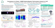
Development of a Pulsed ~100MW Rotating Magnetic Field Ionization System for C-2W
Erik Trask1, I. Allfrey1, E. Granstedt1, V. Godyak2, A. Korepanov1, S. Krause1, J. Leuenberger1, Y. Mok1, R. Smith1, T. Valentine1, W. Waggoner1, and the TAE Team1
1 TAE Technologies, Inc., 19631 Pauling, Foothill Ranch, CA 92610 2 University of Michigan & RF Plasma Consulting
Abstract
The Rotating Magnetic Field (RMF) ionization system on the C-2W experiment at Tri Alpha Energy has been substantially upgraded from the previous system on the C- 2U facility[1]. This system is used for ionizing gas prior to forming and accelerating Field-Reversed Configurations in the formation sections. Through the use of enhanced power units with increased stored energy, and an improved antenna design for better power coupling, a fully ionized plasma can now be produced in less than 100 us, in a background axial magnetic field in excess of 0.1 T, while at gas pressures in the ~1 mTorr range. The system design, characterization, and experimental ionization parameters will be discussed.
[1]M.W. Binderbauer et al., AIP Conf. Proc. 1721, 030003 (2016) Goal: Improve Ionization System
Comparisons between C-2U experiments and simulations imply only 10-20% of injected gas was ionized
RMF and ringing theta-pinch (Θ-PI) systems were used for ionization, almost solely due to the Θ-PI
Solution: Upgrade RMF and Retire Θ-PI
RMF ionization system is decoupled from formation by geometry
Axial currents in RMF antenna do not couple to azimuthal formation straps, while azimuthal currents are in opposite directions, reducing net coupling
Voltage coupling from formation to RMF antenna is ~10% due to finite length of the solenoidal fields
RMF Antennas
Theta-pinch coils and headers
Increase Capacitive Coupling To Plasma
Insight: RMF discharge begins with capacitive discharge, switching to inductive mode after the plasma density becomes large enough (thanks to Valery Godyak)
Ionization Test Stand: Develop Antenna Topology
Test Stand: Components from C-2U formation section
Quartz tube and fast straps reused
Axial B field at up to 0.15 T from fast straps connected in series Old pulsed power equipment drives antennas
Gas delivery by either backfill or gas puffs
C-2 vs. C-2W RMF System Comparisons
Θ-PI + 8ms
LamyRidge simulations and fast camera imaging show an annular
RMF: No Light
Θ-PI + 12ms
Θ-PI + 14ms
plasma is produced by the Θ-PI
Ideal ionization distribution is flat in simulations, with enhanced flux
trapping due to heavy field lines near the wall during reversal
Decouple Ionization system from FRC formation circuit
Transient voltage oscillations from the PI circuit cause switches in the main reversal circuit to trigger early. This reduces formation reliability and restricts operating ranges.
Wide, flat antennas increase the electrostatic field inside the formation section Faster Ionization
Antenna width increased from 0.05” to 2”
For the same voltage, electric fields may be 30-60% higher near the walls where ionization is likely to begin
100% ionization is complete in approximately 70ms
Average density measured by interferometry
Oscillatory structure due to rotating plasma relative to line of sight
Light emission precedes rise in density, dropping off as neutrals
density is reduced
Average radial density is flat
Line ratio analysis from
helium doping and fast camera imaging
See BP11.00047 for details
Density is present near wall
and axis
Improved from Θ-PI
Li
Sbi Smr Spi
Cbi Cmr Cpi
Li, Ll: Inductance of Isolation, Load;
Ll
Summary: High Power Ionization System Improves C-2W Initial Conditions
Circuit is decoupled from reversal, with improved pulsed power reliability
Ionization percentage is ~100%, with flat radial distribution
High power circuits are implemented on C-2W (Norman)
Cbi, Cmr, Cpi: Sbi, Smr, Spi:
Capacitance of Bias, Main Reverse, Pre-Ionization; Switch of Bias, Main Reverse, Pre-Ionization Circuit
Implement different antenna geometries
Two antennas: Quadrupole Two antennas: Dipole Some ionization Better ionization
Antenna Parameters
Material
Topology
Operating voltage / Energy
C-2 / C-2U
Center conductor of high voltage (~20kV) coaxial cable
4 (azimuth) x 4 (axial) saddle coils
~18kV, 0.8 kJ per formation section
C-2W
Copper sheet, insulated with silicone rubber and Kapton tape
4 (azimuth) x 2 (axial) saddle coils
~40kV, ~20kJ per formation section
Test Stand Results: Complete Ionization At > 0.1 T
Four antennas: RMF Best ionization
Upgraded Pulsed Power System
Pseudo-spark switches: 40kV x 50kA
High power density
Oscillatory circuit has not caused issues
100kV caps
Voltage reversal does not exceed 40%
Transmission lines and headers improved System capability exceeds 45kV (DC)
C-2W Tests: Gas Distribution Inference
Gas ionization loads antenna, changing damping rate
Puff gas at earlier times. Time of flight changes the distribution
under an antenna
| 1 |
