
Main-Ion Charge Exchange Recombination Spectroscopy on C-2W FRC Plasmas
P. 1
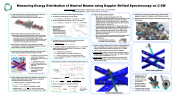
     Measuring Energy Distribution of Neutral Beams using Doppler Shifted Spectroscopy on C-2W
 Ryan Marshall, Erik Granstedt, Deepak Gupta, James Titus, and Juan Aviles
TAE Technologies, Inc., 19631 Pauling, Foothill Ranch, CA 92610
     n 9 neutral beam injectors (8 heating beams and 1 diagnostic beam) are installed on the central cell of C-2W.
n 4/8 beams fixed at 15 keV. 4/8 beams tunable 15-40 keV.
n n
n
n
n
n n
n
Taking a closer look at the beam energy components: 1x Diagnostic Neutral Beam (7 A): H, 40 keV
n𝑬𝟏 =𝟒𝟎keV,𝑬𝟐 =𝟐𝟎keV,𝑬𝟑 =𝟏𝟑.𝟑keV,𝑬𝟒 =𝟐.𝟐keV. 8x Heating Neutral Beams (120 A each): H or D, 15 keV.
n𝑬𝟏 =𝟏𝟓keV,𝑬𝟐 =𝟕.𝟓keV,𝑬𝟑 =𝟓keV,𝑬𝟒 =𝟎.𝟖𝟑keV(H).
Cross sections for the beam projectile to interact with background target gas and emit Balmer-alpha is a function of energy.
[1] Hunter et al. Atomic Data For Fusion. 1990
[2] Williams, I.D., Geddes, J., and Gilbody, H.B. J Phys. B. 1982
Finding beam current fractions from collected emission spectra by firing beams into neutral gas:
𝐴%=&!&"'(")"=&!𝑛%𝑣%𝜎𝐸% =𝐶𝑛%𝑣%𝜎𝐸% *+ *+
𝑨𝒊 = Balmer-𝜶 emission rate [photons per
energy component is proportional to the number of counts measured by the detector.
n 𝒏𝒈 = background gas density [m-3].
n 𝒏𝒊 = beam density in the ith energy component [m-3].
n 𝒗𝒊 = speed of neutrals in the ith energy component [m/s].
n 𝝈 𝑬𝒊 = cross section for Balmer-𝜶 emission of the ith energy
component [m2].
Experimental Calculation of Heating Neutral Beam Fractions 𝒇𝒊
n Future measurement system:
n Why replace a system that already works? The measurement system described in the green panels was not designed for this measurement. It is a main ion charge exchange spectroscopy diagnostic and it is needed for its original purpose. Current system also only sees 4 heating beams, we want to monitor all 8.
n Project: Design a new diagnostic to measure the doppler- shifted Balmer-alpha emission from all eight primary neutral beams in C-2W at the same time and on a regular basis.
n Why: To maintain and improve the neutral beam energy distribution while providing the most up-to-date data for analysis and simulation.
n How: Fully automate beam energy spectrum measurement with millisecond time resolution using off-the-shelf spectrometers.
n 5x Avantes Starline AvaSpec- ULS2048L-EVO spectrometers
n Panel to the right and below show the lines of sight (light blue) that this new diagnostic will use to see the north and south heating neutral beams through the starred (*) 8” CF flange.
n 5 lines of sight required to collect light from 8 beams.
n North beams are easier to intersect. Two collimators required
at slightly different angles, each intersect two different beams to cover all four north beams: 1, 2, 7, 8.
n South beams are harder. One collimator can intersect both beams 4 and 6. Beams 3 and 5 are the hardest, each require separate lines of sight.
n Potential port location for beam energy measurement diagnostic (yellow *). Slightly north of machine center.
n Heating neutral beam injection directions shown by light blue arrows.
      *
 n Neutral beam injectors accelerate particles as ions. Neutralization and dissociation take place after accelerating.
n The neutral beams have a primary (full energy) component from accelerated H, a secondary (half-energy) component from accelerated diatomic H2, a tertiary (third-energy) component from accelerated triatomic H3, and a quaternary (1/18 or 1/10 energy) component from accelerated water molecules.
n Measuring the neutral beam energy fractions accurately
is essential to understand and quantify the impact of neutral beam injection on many fusion plasmas.
n Light collection is accomplished using an f1.8 spectrometer with 5 input optical fibers stacked vertically at the slit.
𝐦𝟑 5 𝐬 5 𝐒𝐫 ] in the ith
        Main mount
Alternative mounts n
The 5 fibers can be interchanged on the three toroidally and axially displaced mounts around the machine.
n 35 different views in total.
4 of the 8 heating beams and diagnostic neutral beam can be diagnosed.
Lines of sight that do not intersect beams provide background and noise information.
NB1 NB2
   n
n
𝐶𝑜𝑙𝑑 𝐻
𝐸/3
𝐸/2 𝐸 𝐸/18
NB8
NB7
    Diagnostic
neutral beam (DNB)
Heating neutral beams (NBs)
NB3
North Heating Beams
n Close-up of an 8” CF Viewport with 8” CF Pneumatic Shutter.
n Shutter paddle limits lines of sight.
n Modified paddle for maximum opening. Actuator rotatable.
n Turquoise tubes represent optical fiber lines of sight.
H𝛼 emission E = 15 keV H beam
NB4
      n Neutral beam energy distributions obtained by measuring the Doppler-shifted Balmer-alpha emission due to collisional excitation during beam-in-gas shots.
n 𝑯: Beam projectile. 𝑯 : Background gas, target. 𝟐
n𝐻+𝐻/→𝐻+𝐻/+ Balmer−𝛼
n 𝐁𝐚𝐥𝐦𝐞𝐫 − 𝛂 can come from projectile or target.
nDopplershift:𝜆=𝜆0 1+)1𝑐𝑜𝑠𝛩 where𝜽istheangle between neutral beam direction and detector line of sight.
# 𝝀#𝝀𝟎 𝟐 nFitpeaksto𝑮 𝝀 =𝑵𝒆 𝟐𝝈𝟐
→𝑨𝒊 =∫. 𝑮 𝝀 𝒅𝝀= 𝟐𝝅𝑵𝝈. -.
 n𝜑=𝑛𝑣=4!,𝑓=8! =4!⁄67!
3 33 567! 3 ∑$ 8! ∑$ 4!⁄67!
NB6 NB5
!"# !"#
n Chord 3 Calculation for 𝒇𝒊 (current fractions):
Peak Amplitudes:
𝐸: 𝐴! =29.1
𝐸⁄2 : 𝐴" = 9.23
𝐸⁄3 : 𝐴# = 2.57
Current Fractions:
𝑓! =0.707
𝑓" = 0.235
𝑓# = 0.058
Goodresults, agree with past estimates.
 South Heating Beams
| 1 |
