
Tobin-HTPD-2020-poster
P. 1
• • •
• SVD generalizes eigen decomposition to non-square matrices: 6×8 . = 0ΣU3
. ∈ R is a 2D data matrix (time x space)
0 ∈ R6×6; - ∈ R8×8; Σ ∈ R6×8 is a diagonal matrix of singular values • HOSVD extends this to third (and higher) order tensors [10]
Mode Shape Vectors
Mode Phase Plots:
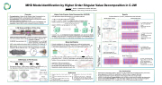
MHD Mode Identification by Higher Order Singular Value Decomposition in C-2W
Overview
First application of Higher Order Singular Value Decomposition for
MHD mode identification using magnetic field measurements
First application of an SVD-based method for this purpose in FRCs (previously applied in tokamaks [1, 2, 3])
The method presented offers improved computational efficiency and resolution of global MHD modes compared to previous methods
M. Tobin, T. Roche, T. Matsumoto, and the TAE Team
TAE Technologies, Inc., 19631 Pauling, Foothill Ranch, CA 92610 Higher Order Singular Value Decomposition (HOSVD)
Results
Analyses based on !" and -" except where noted otherwise
- -
-
From -":
2 zero-crossingsèN = 1 Mode vectors 90° out of phase
From -L:
!" is odd; !L is evenàWobble
From -":
- 4 zero-crossingsèN = 2
- Mode vectors 45° out of phase
•
•
•
• •
•
• •
Field-reversed configuration: compact torus plasma with low toroidal field and poloidally closed magnetic field lines within a separatrix [4]
Lifetimes of ~30 ms
C-2W FRC key parameters [5]: Total temperatures (QFRD) ≤ 3.0 keV
Electron densities of 1-3×10¹⁹ m-3 MHD modes stabilized by plasma guns, end biasing, FLR effects [6, 7]
Mirnov array: 8 rings of 8 probes each that measure !̇ , !̇ , !̇ [8] T"#
Symmetric about midplane; rings ~ 50 cm apart, probes ~ 45° apart
!" analysis:
Diverters
Confinement vessel
Neutral beams
Formation sections
C-2W Device and Mirnov Probe Array
×;
-CDEF
. = Σ ×: -: ×; -; ×< -< (... ) • Apply to 3D Mirnov array dataset (@ x , x time)
-#
@. ,
• Columns of -A are normalized, linearly independent, and describe the mode shapes in the B dimension; Σ indicates mode strengths; all real-valued tensors
• -": toroidal mode shapes, -#: longitudinal mode shapes, -CDEF: time evolution Mode Identification
• Periodic oscillations in !" (and !#) signals when rotational mode present
• Plasma symmetry across midplaneàsymmetry in !#, antisymmetry in !" [9] • 8 azimuthally spaced probes à resolve up to toroidal mode number N = 4
-" ×: Σ ×<
!" analysis:
!# analysis:
- -
- - -
-
!": All North rings in phase, 180° out of phase with South
Agrees with odd mode vector in -#
!#: Rings in phase across midplane
180° phase shift at FRC axial boundary
Agrees with even mode vector in -#
!": All North rings approximately in phase; 180° out of phase with South
!" and !# : North and South rings in phase; no phase shift at FRC axial boundary
Can be used to determine if FRC is present
Consistent with kink instability
S4
S3
S2
S1 N1 N2 N3 N4
- "0=
(a) (b) (c) '(° • Two vectors (a) with a phase difference of 90° in time and )
Confinement vessel
θ
R Z
Cross section
Mirnov probe
(d)
Mode Phase Plots: !# analysis:
Key Conclusions
in space (b) are projected into the * − , plane (c) and added to describe each rotating mode (d)
!" analysis:
MHD Modes in FRC Plasmas
• Number of zero-crossings in toroidal mode vector = 2 x toroidal mode number • Analyzed in 500-μs-long windows
• FFT used to extract mode frequencies
• Mode shapes are global (same for all rings) • Magnitudes, phases evaluated at each ring:
References
-
- -
FRC axial symmetry and field line twisting à HIJG = HIJG HING
= − HING HK ML
HK L HK ML HK L
Bulk plasma rotationàglobal macro-instabilities; oscillations in !L, !"
Can degrade confinement or lead to collapse of FRC [9] Toroidal Mode Number Toroidal Mode Number
n=2 n=1
Axis of Rotation
(External) Tilt:
O*−P =−O*P O!" P =O!"(P)
O!L −P =−O!L(P)
Wobble:
O*−P =O*P O!" −P = −O!" P O!L −P =O!L(P)
[1] C. Nardone, Plasma Phys. Control. Fusion, 34, 1447 (1992).
[2] J. S. Kim et al., Plasma Phys. Control. Fusion, 41, 1399 (1999).
[3] M. J. Hole and L. C. Appel, Plasma Phys. Control. Fusion, 49, 1971 (2007).
[4] M. Tuszewski et al., Nucl. Fusion, 28, 2033 (1988). [5] H. Gota et al., Nucl. Fusion, 59, 112009 (2019).
[6] M. Tuszewski et al., Phys. Rev. Lett., 108, 255008 (2012).
[7] L. Schmitz et al., Nat. Commun., 7, 13860 (2016).
[8] T. Roche et al., Rev. Sci. Inst., 89, 10J107 (2018).
[9] Y. A. Omelchenko et al., Phys. Plasmas 8, 4463 (2001). [10] L. De Lathauwer et al., SIAM J. Matrix Anal. Appl. 21,
1253-1278 (2000).
•
• • • •
Rectangular arrangement of Mirnov probes on C-2W, facilitated by the simple geometry of the FRC, allows application of HOSVD for identification of MHD modes in magnetic field data Fourierdecompositionassumesthebasisvectorshapes;SVDusesaneigenbasis HOSVDiscomputationallymoreefficient,asall64Mirnovprobescanbeanalyzedsimultaneously Global modes better identified on rings with weaker signals when all rings are analyzed together Allows clear observation of N = 1 phase shift of 180° at FRC axial boundary (x-points)
Vessel Wall
Mirror Plasma n = 1 n = 2 n = 1 Wobble mode (shot 116998) (shot 120599) (shot 119839)
Normalized O!
time
| 1 |
