
Page 4 - Tomographic imaging system for measuring impurity line emission in a field-reversed configuration
P. 4
022506-4 D. C. Barnes and L. C. Steinhauer
Phys. Plasmas 21, 022506 (2014)
density. We also use the same definitions as those of Ref. 7 for the dimensionless rotation parameter
a1⁄4 X; x ð1 sÞ
s1⁄4 Te : Te þ Ti
(15)
The diamagnetic frequency is here unambiguously defined as
x 1⁄4 Xe X; (16)
since both species rotation frequencies are uniform, there is no ambiguity in defining x . Positive B is in the z direction, so ion diamagnetic rotation is in the negative h direction in our convention.
We have chosen s 1⁄4 0:25 consistent with modern FRC parameters, but have also confirmed that results are inde- pendent of s as shown in Ref. 7.
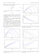
Results for ‘ 1⁄4 1 and ‘ 1⁄4 2 modes are shown in Figs.
1–4. The normalization is as in Ref. 7, with VA the Alfven
velocity computed with the central (maximum) density and
the external magnetic field. Plasma profiles also agree with
those of Ref. 7, with number density given by 2 2 2 1pffiffiffiffiffiffiffiffiffiffiffiffiffi
n=n0 1⁄4sech r =r0 þc =b0, c1⁄4tanh 1 b0. As in Ref. 7, we have chosen b0 1⁄4 0:75 and the plasma radius, defined by the equivalent sharp boundary plasma with the same line density as a 1⁄4 0:2rw.
FIG. 1. Normalized growth rate (a) and real frequency (b) vs. normalized wave number for ‘1⁄41 mode with negative a ( 0.2, 0.4, 0.6, 0.8, 1.0; bottom to top curves).
FIG. 2. Normalized growth rate (a) and real frequency (b) vs. normalized wave number for ‘ 1⁄4 1 mode with positive a (1.2, 1.4, 1.6, 1.8, 2.0; bottom to top a curves, top to bottom b curves).
FIG. 3. Normalized growth rate (a) and real frequency (b) vs. normalized wave number for ‘ 1⁄4 2 mode with negative a ( 0.4, 0.6, 0.8, 1.0; bot- tom to top curves).
