
Page 5 - untitled
P. 5
RAHMAN et al.: HYBRID MHD MODEL FOR A DRIVEN, ION-CURRENT FRC
3141
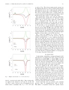
Fig. 3.
Midplane current densities, at t = 50, 100, and 150 μs.
as early as 50 μs. The velocity remains nearly constant over the simulated time interval, as the (not shown) plasma density and temperature increase, due to radial and axial compression. The rigid-rotor plasma ring is well-established by 100 μs. The velocity contours indicate that a rotating plasma ring is present inside the background-magnetized plasma, with a plasma pressure that is almost 2–3 three times larger.
The negative-flow velocity arises from the inductively- applied electric-field, described by (19). The flow velocity changes sign in a narrow region outside the rotating FRC, due to a diamagnetic drift. The drift is due to a gradi- ent in the plasma pressure at the outer edge, in the ion- diamagnetic direction. From the azimuthal-velocity contours, at 100 and 150 μs, the ion diamagnetic drift velocity is, Viθ ≈ 2.0 × 106 cm/s, roughly an order of magnitude smaller than the velocity inside the FRC, but on the same order as measured by [3]. In the experiments Doppler-spectroscopy is used to measure the azimuthal flow, using the emission lines of high-Z impurities; due to their large gyroradius the high-Z impurities are more likely to exist in this outer layer.
Fig. 3 shows the midplane ion-, electron-, and total- azimuthal current densities, at 50, 100, and 150 μs. The ion current is calculated from, Ji = enviθ , using the actual density and velocity, while the electron current is calculated using Ohm’s law. The simulation shows that the ion-current density dominates from the beginning of the simulation and is much narrower radially. The electron current that develops eventu- ally, due to collisions between ions and electrons, reduces the ion current. As the FRC equilibrates the plasma heats and the collision frequency decreases. During this time, the electron current remains relatively constant. The net integrated current over the region of simulation is 28.86, 29.31, and 33.93 kA at 50, 100, and 150 μs, respectively. Harris et al. [3] reported 15 kA using a Rogowski current probe.
IV. DISCUSSION
A finite plasma, embedded in a background magnetic field, and subjected to an applied-electric field, cannot be described adequately by standard MHD, or reduced MHD, since the electric field is absent in the force equation. In these models the electric field arises through Ohm’s Law, which assumes that the total current is due only to electrons. In addition, the effects of the finite particle gyro-orbits are neglected.
The force applied by the electric field in a weakly- magnetized plasma will accelerate electrons and ions differ- ently, due to the large difference in their gyro-orbit size. In the present example, the ion-Larmor radius is, ρi = 1.6 cm, and the electron-Larmor radius is, ρe = 0.04 cm. The azimuthal- electric field produced by the flux coil accelerate electrons in the first half of the gyroperiod and decelerates them in the second half of the gyroperiod. Thus, their net acceleration is zero over the entire gyroperiod. In the presence of crossed electric and magnetic fields, the electrons can drift radially, causing a charge imbalance that is compensated by the flow of electrons along the magnetic-field lines.
On the other hand, ions can accelerate in the azimuthal direction, when an azimuthal-electric field is present. This induces a net-plasma rotation and a plasma current,
field, Bz , are plotted on the right of Fig. 1. These radial profiles are similar to the solutions of (12) and (13), for the 1-D case. Fig. 2 shows contours for the ion-azimuthal velocity, which reaches a maximum value, Viθ = 2.0 × 107 cm/s,
