
Page 3 - Characterization of compact-toroid injection during formation, translation, and field-penetration
P. 3
11D409-3
Roche et al.
Rev. Sci. Instrum. 87, 11D409 (2016)
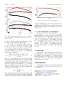
FIG.4. Tracesfromthevariousmagneticsignalsatz= 25cm.(a)Induced currents, (b) internal Bz, (c) external Bz, and (d) resulting r . Blue trace is without correction.
(See Fig. 3). This can be done for every shot as both external probes give accurate readings for the DC field.
If we assume the total magnetic flux in the sys-
FIG. 5. r (a) with active currents driven in ExFCs (b).
current of the ExFC and Bex2 follows the current induced in the DC magnet coil. The latter is the signal that represents the flux that has escaped the system and what will be used to determine r .
V. PLASMA PERFORMANCE ENHANCEMENTS
The achievement of the C-2U milestone was accom- plished due in part to actively driving current in the ExFCs. After attempting several configurations it was found that increasing the magnetic pressure in the central region of the vessel led to very long-lived (>11 ms) FRCs as shown in Fig. 5. This high performance regime was attained before the new array of B-Dots probes were installed; so the traces in Fig. 5 are not corrected for flux leakage. Therefore, the plasma lifetime/radius are slightly longer/larger than depicted.
tem is the same for both plasma and vacuum shots,
22 i.e., (t)= (t), with (t)=⇡ r r B
plasma v plasma w in + ⇡ rc2 rw2 Bex, then we can derive an expression for r that is compatible with all of the various configurations of the ExFCs. Taking into account all of the available field measurements, we determine
VI. CONCLUSION
Enhancement of flux confinement led to longer-lived, sustained plasmas. Some C-2 magnetic diagnostics were not compatible with the upgraded C-2U system. Additional magnetic measurements were employed to provide an accurate representation of r and accordingly, other parameters derived from pressure balance.
ACKNOWLEDGMENTS
We thank our shareholders for their support and trust, and all fellow TAE sta↵ for their dedication, excellent work, and extra e↵orts.
1M. W. Binderbauer et al., Phys. Plasmas 22, 056110 (2015).
2M. C. Thompson et al., Rev. Sci. Instrum. 83, 10D709 (2012).
3L. C. Steinhauer, Phys. Plasmas 18, 070501 (2011).
4C. A. Romero-Talamás et al., Rev. Sci. Instrum. 75, 2664 (2004). 5W. Rogowski and W. Steinhaus, Arch. Elektrotechnik 1, 141 (1912). 6M. Tuszewski, Phys. Fluids 24, 2126 (1981).
r2 2 shBi hB,i+ c/r 1 (B B )
r=rininvwexex,v,(2) w B0 + hBini
where rc is the DC magnet coil radius, rw is the vessel wall radius, B0 is the DC magnetic field, and Bin and Bex are the field perturbations due to the plasma just inside the vessel wall and just outside the ExFC respectively. The brackets (hi) represent an average of all available probes at a particular axial location (Mirnov array) and the v subscript denote the vacuum shot fields. Additionally, the external field Bex is the scaled Bex2 as discussed above, i.e.,
Bex(t)= Bex1(0)Bex2(t). (3) Bex2 (0)
This calculation is performed for all 19 axial locations of the internal probe array. The product of this analysis is displayed in Fig. 4. As expected, the field measured by Bex1 follows the
