
Page 2 - untitled
P. 2
Research Article
Vol. 55, No. 21 / July 20 2016 / Applied Optics 5581
Fig. 1. Typical optically pumped FIR laser resonator.
and the mesh [13]. However, it is enclosed inside the vacuum chamber, making it inconvenient for optical alignment.
Common to the above-mentioned output couplers is that they also serve as the reflector for the CO2 pump laser beam. Due to the finite length of the FIR laser cavity, the absorption of the pump laser requires multiple passes. For example, the absorption coefficient of the 9R20 line of CO2 laser in the formic acid (HCOOH) vapor with a pressure of ∼400 mTorr is 0.36 m−1[14], and four passes are required to absorb 90% of the pump power in a FIR cavity length of 1.5 m. As the pump laser is usually injected via an off-axis hole in the rear mirror, the normal of the pump beam reflector needs to be at a small angle with respect to the waveguide axis for optimum excitation. On the other hand, FIR laser alignment requires that the reflecting surface of the output couplers be perpendicular to the waveguide axis. Therefore, the excitation of the laser is compromised by the FIR laser alignment.
In our new FIR laser design, the pump beam reflector and the FIR output coupler are separate components, as shown in Fig. 2(d). The substrate is a crystal quartz plate with the thick- ness chosen to have maximum transmission at the FIR wave- length, while it is coated to provide >98% reflection for the pump laser, making it a dichroic mirror. The adjustment of the dichroic mirror optimizes the pump beam absorption without compromising the FIR laser cavity alignment. It also is used as the vacuum window, as shown in Fig. 3. A par- allel mesh Fabry–Perot [15] is used as the output coupler [Fig. 2(d)]. It is installed outside the vacuum boundary (Fig. 3), making it convenient to tune and align the laser.
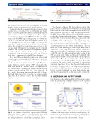
Fig. 2. (a) Schematic of hybrid hole output coupler. (b) Hybrid metal mesh dielectric coupler. (c) Substrate etalon metal mesh Fabry–Perot coupler. (d) New parallel metal mesh Fabry–Perot cou- pler with separate dielectric coated substrate pump beam reflector.
Fig. 3. New FIR laser schematic.
The schematic of the new FIR laser is shown in Fig. 3. The pump source is a GEM Select-50 Coherent CO2 laser grating tuned to the 9R20 line with CW output power of about 58 W, which is split into two beams to pump two identical FIR lasers. Each FIR laser is filled with formic acid (HCOOH) vapor to produce the 433 μm wavelength radiation. The support frames (item 6 in Fig. 3) of the laser have holes and connectors for the working gas and cooling water flows. The FIR resonator con- sists of the rear mirror (item 3), the waveguide (item 11), and the external output coupler (item 9). The waveguide is a 1.52 m long Pyrex tube with 38 mm inside diameter. The rear mirror is a 50 mm diameter gold-coated copper mirror with a 4 mm hole for the pump laser beam injection. The hole is 8 mm off-center, and it is a compromise between minimization of the FIR cavity loss and maximization of the overlap of the FIR laser cavity mode volume and the pump beam path. The dichroic mirror (item 8) is separated from the output coupler as discussed above. Both the rear mirror and the dichroic mirror are mounted to the ends of the bellows (item 4) to allow angle adjustments. The output coupler is mounted on a motorized translation stage (item 10), so that the cavity length can be adjusted for resonance and for controlling the beat frequency between the two FIR lasers. Items 1, 2, 5, and 7 in Fig. 3 il- lustrate the pump beam path, the pump beam entrance win- dow, the O-ring seal, and the cooling water jacket, respectively.
3. LASER GAIN AND OUTPUT POWER
One advantage of the parallel mesh Fabry–Perot output coupler is that the transmission (coupling) coefficient can be varied by adjusting the spacing between the meshes, as shown in Fig. 4.
Fig. 4. Transmission (blue), reflection (green), and absorption (red) coefficients of the output coupler as a function of mesh spacing s, cal- culated based on the transmission line model [15]. Measured power transmission coefficients (squares) also are shown. The meshes have a density of 150 lines per inch with wire width of 30 μm.
