
Page 4 - Drift-wave stability in the field-reversed configuration
P. 4
092518-4 Onofri et al.
Phys. Plasmas 24, 092518 (2017)
FIG. 2. Density contours and magnetic field lines for a simulation with b 1⁄4 0:8 at t 1⁄4 6 ls.
Lamy Ridge equilibrium code.40 The FRC has a separatrix radius Rs 0:4 m and a length Ls 4 m. The closed field region is surrounded by a thick scrape off layer (SOL), which is confined axially by two magnetic mirrors. The initial con- dition for the mirror trap is obtained from fast resistive dissi- pation (with high numerical resistivity) of the same equilibrium, until the closed magnetic configuration is lost. After about 10l s, no closed field lines exist, and the result is used as the initial condition for the mirror trap simulation. The density contours and magnetic field lines of the initial conditions are shown in Fig. 4 for the two cases.
For both simulations, we used a spatial resolution of 150 grid points in the radial direction and 401 grid points in the axial direction. Both simulations are done using classical
FIG. 3. Confinement time ^s vs. b. Dots represent simulation by Brunel and Tajima;22,23 circles represent simulations by Brackbill;17 solid curves repre- sent the theory by Brunel and Tajima;22,23 broken lines labeled TW, WM, and FW represent theories from Refs. 18–21; square dots between error bars represent SCYLLA experiments in Refs. 15 and 16; and red asterisks repre- sent our simulations. Most of the data are shown and taken from Refs. 15–17 and 22 and 21 except for the present work in red asterisks. This figure is built upon the one in Ref. 23.
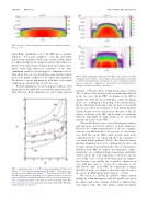
FIG. 4. Initial equilibrium conditions for the FRC (top) and mirror (bottom) simulations before outflow occurs. Density contours and magnetic field lines are shown. Note that in these contour plots, the scales of radial and axial dis- tances are different to emphasize the visual clarity for the radial structure. Similar scale differences in Fig. 5 are shown.
transport coefficients and no neutral beams and no neutrals. The evolution of the density profile is considerably different in the two cases. In the FRC, the plasma in the SOL is quickly lost, while the closed field lines confine the plasma in the core, resulting in a steepening of the density profile. On the other hand, in the mirror trap, the lack of closed field lines does not allow the formation of steep density gradients and the density decreases much faster. Because of this, the density evolutions of the FRC and the mirror are markedly different, particularly the high density in the closed flux region in later times for the FRC.
The parallel flow becomes sonic at the magnetic mirrors and supersonic beyond the mirrors in both simulations. However, the confinement properties of the two configura- tions are very different due to the presence of closed mag- netic field lines in the FRC, which provide much better confinement in the core region and allow the formation of very sharp density gradients. On the other hand, the mirror machine simulation shows poor confinement properties, and it cannot sustain steep density profiles. The closed magnetic field lines in the FRC also improve the temperature confine- ment in the core, resulting in higher temperatures and higher outflow speed. The total temperature is shown for the two cases in Fig. 5 at t 1⁄4 0.2 ms: In the mirror trap, the tempera- ture decreases very quickly due to parallel conduction on open field lines, and at t1⁄40.1ms, the temperature is less than 200eV, while in the FRC, the temperature is higher than 900 eV in the core. Figure 6 shows the axial velocity at the axis for the FRC and the mirror trap at t 1⁄4 100 ls.
We saw in Sec. III that in a plasma column confined radially by a uniform magnetic field, the parallel velocity at the ends is equal to the sound speed. When we add two mag- netic mirrors at the ends of the plasma column, the plasma
