
Page 6 - Drift-wave stability in the field-reversed configuration
P. 6
092518-6 Onofri et al. Phys. Plasmas 24, 092518 (2017)
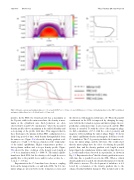
FIG. 8. Density contours and radial profiles at z 1⁄4 0. (a) and (b) FRC at t 1⁄4 0.1 ms. (c) and (d) Mirror at t 1⁄4 0.1 ms. (e) Radial profiles for the FRC (solid lines) and mirror (dashed lines) at t 1⁄4 0 (black) and t 1⁄4 0.1 ms (red).
profiles. In the FRC, the density profile has a maximum at the O-point, while in the mirror machine, the density is max- imum at the cylindrical axis. Such behaviors are often observed in C-2 and C-2U experiments,5 where the measured density profiles show a maximum at the null-field radius and a steepening of the profile with time. This suggests that in those discharges, the plasma held an FRC configuration for a fairly long period of time, with density distinguishable from the mirror case. Figure 9(a) shows the density gradient scale length at z 1⁄4 0 and t 1⁄4 0.5 ms as a function of the temperature of the initial equilibrium. Higher temperatures produce a faster plasma outflow and a steeper density profile. Figure 9(b) shows the time evolution of the density scale length at z 1⁄4 0 for a simulation with Ti 1⁄4 1000 eV. The initial equilib- rium has a thick SOL, but the density scale length decreases quickly due to the parallel losses and it reaches a value Ln 1 cm at t 0:5 ms.
Experiments in the C-2 machine have shown a coupling between the transport in the core and in the SOL.5 In C-2, two mirror plugs are present between the formation sections and
the divertors, with magnetic fields up to 2 T. When the parallel confinement in the SOL is improved by changing the mag- netic field in the formation regions and mirror plugs, the per- pendicular confinement time is also increased, and the FRC lifetime is extended. To study the effect of the magnetic plugs, we did a simulation of C-2, with the correct geometry and magnetic field, including the mirror plugs. Figure 10 shows the initial equilibrium density and magnetic field lines for the C-2 simulation. The C-2 geometry includes the formation sec- tions, the mirror plugs, and the divertors. The results show that the mirror plugs have the effect of reducing the parallel particle flux, and the density gradient scale length is much larger than in the simulations with no mirror plugs. However, Ln is still smaller than observed in experiments, as shown in Fig. 11. Experiments show4 that the density gradient increases with time due to parallel losses in the SOL. When a critical density gradient is reached, the density fluctuation level in the SOL starts to increase. The development of turbulence is fol- lowed by a relaxation of the density gradient due to the enhanced radial turbulent transport. This in turn leads to the
