
An Interesting Poster to look at from the Tri Alpha Energy Team in California
P. 1
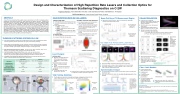
Design and Characterization of High Repetition Rate Lasers and Collection Optics for Thomson Scattering Diagnostics on C-2W
Angelica Ottaviano, Tania Schindler, Kan Zhai , Erik Granstedt, Eli Parke and Matthew C. Thompson
TAE Technologies, Inc., 19631 Pauling, Foothill Ranch, CA 92610
Beam Profiling at TS Measurement Region
Beam profile must be focused to within 2 mm diameter for optimal light collection into the fiber bundle surfaces.
Focus at 305cm with 0.7±0.15mm beam diameter and eccentricity ~1
Focus at 300cm with 0.57±0.1mm beam diameter and eccentricity ~1
FAST CAMERA PULSE PROFILES [CENTRAL LASER, MODE 3]
Phantom v5.2 camera was used to resolve beam profiles of the central laser’s 1kHz pulse chains.
Centroid shift around focus and widening of lineout profile
Centroid shift and widening of lineout profile
Fast camera images reveal beam defocusing over a 35 pulse train.
Rod heating causes a change in beam divergence due to thermal lensing.
At 35th pulse, YAG beam is ~1.1mm in diameterstill is covered in the region of the back projected fiber image.
Synchronization Output
The polychromator electronics require a synchronization pulse to accurately time the integrator gate.
Both laser synchronization signals are 1.0μs before the optical pulse with < 1.0ns jitter time.
Synchronization was verified using a fast NI Digitizer and a delay pulse generator outputting a 40ns wide delayed pulse against the actual optical laser pulse picked up with a diode.
HIGH REPETITION RATE Nd:YAG LASERS
CENTRAL PLANE LASER
1064nm Nd:YAG laser with HeNe alignment laser.
Six amplifier stages generate output energy ~2.0J
per pulse.
Three operating modes:
MODE 1: 31 pulses at 1kHz
MODE 2: 6 pulse burst at 13kHz or 4 pulse
burst at 20kHz
MODE 3: 30 pulse train at 1kHz with a Mode 2 burst replacing any pulse for a total of 33 or 35 pulses.
JET REGION LASER
1064nm Nd:YAG laser with HeNe alignment laser. 4 pulses at 100Hz with >2.0J per pulse.
FEATURES OF OPTICAL PATH THROUGH CV:
Auto alignment camera and motorized mirror system GuideSTAR II implemented.
Two glass wedges installed at laser output to measure ~0.6% of energy from 1st reflection with a fast pyroelectric energy detector Gentec-eo Mach 6.
Half wave plate for polarization optimization for Brewster incidence at the entrance and exit windows.
Focusing lens installed at its FL (3.0m) from the center of TS measurement region.
CENTRAL SYSTEM LAYOUT
ABSTRACT
A new Thomson scattering (TS) system is being constructed on C-2W for obtaining electron temperature and density profiles with high temporal and spatial resolution. Validating the performance of the TS’s custom designed system components is crucial to obtaining reliable Te and ne profiles of C-2W’s plasma. The diagnostic has two systems: one for measuring the central FRC, and one for measuring C-2W’s open field line jet region [1][2]. The custom designed collection lens for C-2W TS system are made of two doublets with image spots of all field points being within 100μm radius and a fast numerical aperture (NA) of 0.24 that matches the coupling fiber bundles and polychromators. The high repetition Nd:YAG laser system can generate 4 pulses at 20kHz or 30 pulses at 1kHz with 2J per pulse. With comparison to design specification, we have examined and characterized the imaging properties of the collection lens, the focused laser beam profiles in the TS measurement region at different operating frequencies, beam pointing stability, and beam divergence.
COLLECTION OPTICS
Double lens set on adjustable translation/rotation stage for general system alignment, including Rayleigh scattering intensity calibrations.
Wide field angle to cover radial ranges of measurement.
Scattered light has broadband nature of 850nm < λ <1070 nm10eV < Te 2keV.
The final lens design is two achromatic doublets, each made of two components:
1. Crown BK7 glass has positive power and low dispersion element. 2. SF1 glass has negative power and high dispersion element.
Zemax Optical Studio
Software used to minimize spot diagrams for different field positions at λ = 1064nm and 850nm.
Actual measurements of the image plane were compared.
Setup: a HeNe source with and an overfilled fiber cable of Ø = 600μm at 1.0m from the lens on an adjustable vertical rail.
Good agreement of image plane model and experiment
THOMSON SCATTERING SYSTEMS ON C-2W
Two systems designed to measure the core FRC plasma across C-2W’s mid-plane/central region (currently operational) and the open field line ‘jet’ region (commissioning underway).
Careful design and characterization of each component of the two systems has been conducted to provide reliable and highly spatially/temporally resolved Te and ne measurements by optimizing the system’s stability, signal strength, misalignment margins, and stray-light control.
HIGH REPETITION RATE Nd:YAG LASERS as light sources deliver multi-pulse bursts to the plasma at ~2.0J energy per pulse, producing strong scattered light signal.
CUSTOM DESIGNED COLLECTION OPTICS provide a wide view angle allowing for measurements to cover the plasma core to the plasma edge across 16 (central) and 5 (jet) radial locations. 30m long custom designed silica fiber bundles transmit light to a detection system.
5-CHANNEL POLYCROMATORS WITH APD MODULES detect the scattered signal for spectrum analysis. A spectral calibration will be performed on each unit [3].
Central Plane
Jet Region
Light Source
1064nm Nd:YAG laser, 30-35 pulses at 1kHz with 2.0J/pulse
1064nm Nd:YAG laser, 4 pulses at 100Hz with >2J/pulse
Spatial Resolution
16 locations
5 locations
Beam Path Length
~7.0 m
~10.0m
Collection Length
2.5cm
1.5cm
Collected Photon Number
~1.6×10⁵ at ne=1013/cm3
~3.5×10⁵ at ne=1013/cm3
Distance between laser beam and collection optics
1.00m
0.52m
Polarization
horizontal
horizontal
Central TS
Beam dump and alignment camera enclosure
Focusing lens and entrance baffle enclosure
Jet TS
Beam dump and alignment camera enclosure
Focusing lens and entrance baffle enclosure
Beam path
Collection
optics and alignment stage
Collection
optics and alignment stage
Beam path
Fiber bundles to polychromators
Laser Energies
CENTRAL LASER
Mode 3 is currently used on C- 2W’s plasma with first pulse replaced by a 13kHz 6 pulse burst.
The polarized energy is measured:
Mode 1: 2.05±0.05J average energy.
Mode 3: 2.09±0.05J average energy with 4.7% decrease over pulse train.
JET LASER
2.5J average energy with 0.4% deviation over >100 shots.
Energy decrease in central laser caused by relative changes in amplification to different polarization components.
YAG Pointing Stabilities
The TS systems are sensitive to small alignment changes requires good beam pointing stability. Measurements were taken at focus (3.0m) with GuideSTAR II cameras.
Total Test Time:
3 hours
Stability:
100±5 μrad (x) 63±5 μrad (y)
Total Test Time:
6 hours
Stability:
62±14 μrad (x) 85±15 μrad (y)
Fiber Cable Bundles
22-/220-silica/silica fiber cables, each 30 m in length
Collection area of 1.0×5.0mm
115 fiber per bundle
Transmit light to
polychromators
The numerical aperture (NA) is critical to couple the collected light from the collection optics without losses.
Measured in lab to have: NA = 0.242±0.22
In good agreement with required design specs of 0.26.±0.2.
Acknowledgements
We thank our shareholders for their support and trust, and all fellow TAE staff for their dedication, excellent work, and extra efforts.
References
[1] K. Zhai Thomson scattering systems on C-2W field-reversed configuration plasma experiment HTPD 2018
[2] M. C. Thompson Diagnostic suite of the C-2W advanced beam-driven field-reversed configuration plasma experiment HTPD 2018
[3] T. Schindler Spectral and intensity calibration of a Thomson scattering diagnostic for the C-2W field-reversed configuration plasma experiment HTPD 2018
| 1 |
