
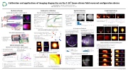
Jet Outflow and Open Field Line Measurements on the C-2W Advanced Beam-Driven Field-Reversed Configuration Plasma Experiment
P. 1
+Z ◦
0.8 0.4 0.0
35 FOV
• nearly orthogonal views enable 3-D localization
+Z
2.5
• port outlines match image data
3.0
4.0
to
• removable for cleaning • sapphire viewport
304SS mirror
at various angles
• LCD orientation of each image
[1] [2] [3]
[4] A. H. Andersen and A. C. Kak. en. Ultrasonic Imaging 6.1 (Jan. 1984), pp. 81–94.
[5] W.H. Meyer, M.E. Fenstermacher, and M. Groth. Vol. 59. Bulletin of the American Physical Society 15. 2014.
λ0 cλ(θ)=
25 0
protective cap around in-vessel for axial view
mirror
re-entrant tube
motorized bellows actuator
• optical system nonuniformity: FNUC (x, y) 0.8
m Z: 0.24
-0.24 m Z: 0.24 -0.24
m Z: 0.24 -0.24
m
0.10
0.15
0.20
0.25
0.30
0.35
fired into gas target
(a)
Calibration and applications of imaging diagnostics on the C-2U1 beam-driven field-reversed configuration device
Mechanical Design
Desired views necessitate re-entrant viewports
Radiometric calibration
Map camera (nonlinear) relative response function:
Spatial Calibration Ex-situ using checkerboard
Sample Applications Track fueling pellets
+Y +X
axial camera
+Y
+X
Retractable for gettering protection
sapphire window
10x 2" dia filter wheel
support electronics
camera black anodizedwith lens
enclosure
• •
• • •
nonlinearity: intrinsic to CMOS,2 gamma correction, dual-slope shutter (EDR)
approach: many exposures of a static scene, iteratively solve for response function and scene ra- diance
N(N)= pe e
N ifN≤d, ee0
d+t/t(N−d) ow. 001e0
(a)
(b) 1.0 0.5 0.0
0.0
side view
top view
• •
• •
• •
generic camera model3 suit- able for wide-angle and fish- eye lenses
extrinsic parameters:
• aperture position
• orientation: pitch, yaw, roll
polynomial radial function
•
Axial Camera
shot: 46163
t: 0.853 ms
exposure: 98.0
pellet: (-0.43,-0.23,-0.36) m
Radial Camera
shot: 46163
t: 0.862 ms
exposure: 18.0
pellet: (-0.43,-0.23,-0.36) m
Axial Camera
shot: 46163
t: 1.053 ms
exposure: 98.0
pellet: (-0.36,-0.19,-0.33) m
0.2 0.4
Radial Camera
shot: 46163
t: 1.039 ms
exposure: 18.0
pellet: (-0.36,-0.19,-0.33) m
xyz
Axial Camera
shot: 46163
t: 1.353 ms
exposure: 98.0
pellet: (-0.14,-0.15,-0.33) m
Radial Camera
shot: 46163
t: 1.305 ms
exposure: 18.0 s
pellet: (-0.14,-0.15,-0.33) m
vz
121◦ FOV radial
• Lrel = Npe(Ne(C(x,y)))/t0
Optical system light throughput nonuniformity:
In-situ using vessel landmarks
Z: 1.03
0.72
0.24
-0.24
-0.72 -1.03
-1.74 -2.67
m
Z:
1.03 0.72
0.24
-0.24
-0.72 -1.03
-1.74 -2.67
1.03 0.72
0.24
-0.24
-0.72 -1.03
-1.74 -2.67
Z: 1.03
0.72
0.24
-0.24
-0.72 -1.03
-1.74 -2.67
Optical System Design Optimized for narrow-band filters, light throughput
0.7 0.6 0.5 0.4 0.3 0.2 0.1 0.0
0.T
• back-projection used as initial guess: ε = εBP = P · b
• 40–60 cm viewport to camera • <73.0 mm dia optics envelope
0.08 0.04 0.00
0.0
0
0.5 0.0
0
5000
10000 datum index Histogram
15000
mean: 1.078 : 1.190
0.0
0.5
0
5000
10000 datum index Histogram
15000
mean: 1.162 : 0.657
0.5 0.4 0.3 0.2 0.1 0.0 0.5 0.4 0.3 0.2 0.1 0.0 0.5 0.4 0.3 0.2 0.1 0.0 0.5 0.4 0.3 0.2 0.1 0.0
t: 1.44 ms
t: 2.46 ms
t: 3.48 ms
t: 4.50 ms
1.0
2.00 r 1.75 1.50 1.25 1.00 0.75 0.50 0.25 0.00
• ≥1.0 nm filter bandwidth achromatic lens-based optical periscope optimized for F/2.0
0.2 0.4 0.6 0.8 Source image data value [arb]
(a)
01234567 01234
imaging lens
100 80 60 40 20
0.02 0.03 0.04 0.05 0.06 0.07 0.08 0.09 0.10 0.11 Target line pairs/mm
H. Gota et al. Nuclear Fusion 57.11 (2017), p. 116021.
Fei Wang and Albert Theuwissen. Electronic Imag- ing. Vol. 2017. 11. Jan. 2017, pp. 84–90.
J. Kannala and S.S. Brandt. IEEE Transactions on Pattern Analysis and Machine Intelligence 28.8 (Aug. 2006), pp. 1335–1340.
06
1 8
2 10 175 3 12
4 150
Viewport transmission tracked in-situ
2.00 1.75 1.50 1.25 1.00 0.75 0.50 0.25 0.00
3.5 3.0 2.5 2.0 1.5 1.0 0.5 0.0
8 6 4 2 0
Detector line pairs/px
(theoretical transmission)
Edgertronic QE
α
relative changes attributed to window trans-
NB3
camera
port CAD geometry mapped to image space using ex-situ spatial calibration SVG file generated with port outlines overlaid on image data
Axial Camera, method: ext+int+2rad
manually
• positive and negative
• spherical abberation
lenses
reduce
0.05
0.10
[px] Residual 4
HP
• residual errors typically ∼10%
1.0 0.8 0.6 0.4 0.2
0.50 0.25 0.00
645
1.00 0.95 0.90
0 2 4 6 8 10 12 0.00 50
1.00
0.98
0.96
0.94
0.92
• • •
NB2
NB1
relay optics
measured unshifted D emission from NBs
mirror adjustment screw
end-cap
Radial Camera, method: ext+int+2rad
•
• •
60 ∑N ∑N 30
vertical data
fit
135°
225°
horizontal data
fit
-90 -60 -30
45°
315°
• •
model parameters numerically opti-
mized to match adjusted port outlines
no in-vessel access required!
perform at each gain setting
N (C)=∑N−1c Ck ek
2-5 params intrinsic parameters:
datums
mapping
mean: 0.472 : 0.361
3.5
adjusted
1.0 1.2
1.0 1.2
0.90 00.0 1.1
350 400
450 500
550 Wavelength [nm]
750
0.88 0.86 0.84
Phantom v5.2 QE
75
NB5
NB4
600 650 700
NB2
NB3
646
647
648
649
650
651 [nm]
0.10 0.05
125
100
256×256 frame
•
• . L (λ) T(λ,θ)dλ
1.0 0.9
0.8 (b)
48500
NB1
Lline = c (θ)Lline ,
λ0
0 bb
rel
rel
• L
T(λ0,θ)
0 50 100 150 px
49000
49500 Shot
50000
50500
bb
∫
k=0
0.8
Time [ms]
0.6 0.8
Time [ms]
measured LCD radiance angular distribution:
r∆Φ
rr r r
k=2 ak|θx|k + solved simultaneously for:
k=2 bk|θy|k
m
r∆Φ
m
m
LLCD(θx, θy) = exp
using full optical system, recorded images of LCD
DCA07A (raw) shot:45838
DCA07A (raw) shot:45838
DCA07A (raw) shot:45838
• λ : spectral line wavelength 0
• L : relative camera response
Lbb: source spectral radiance
rel
T(λ, θ): filter transmission curve
1.5
0.5
0.0 Z [m]
0.5
1.0
1.5
Absolute photon radiance (for each filter):
0.0
Residual [px] Residual [px]
•
0.10
0.05
0.00
256×256
Compare emissivity reconstruction with magnetics
px
NB5
E.M. Granstedt, D. Fallah, M. Thompson, the TAE Team
TAE Technologies, Inc., 19631 Pauling, Foothill Ranch, CA 92610
ve Transmission
MTF [%]
Wide-angle radial view
Nearly axial view
Transmission or QE
Kernel Integral
Transmission
Kernel [nm]
650.0 nm spectral line relative transmission
Relative Transmission
R [m]
R [m]
R [m]
R [m]
W/m3
W/m3
O1+3p 3s
Ar1 + 4p(2F) C2+3p 3s Ar1 + 4p(2D)
4s 4s
O5+8 7
O4+3d 3p H/D-
He0+ 3d 2p
He0 + Ar0 + He0 +
3s(3S) 4p(2F) 3s(1S)
2p 4s 2p
W/m3
W/m3
RMS Error
Source image data [arb]
Source fit residual [arb]
NUC
t: 0.988 ms [0.939,1.037 ms]
t: 0.993 ms [0.795,1.192 ms]
t: 3.822 ms [3.773,3.871 ms]
t: 3.793 ms [3.595,3.992 ms]
t: 5.817 ms [5.768,5.866 ms]
t: 5.794 ms [5.595,5.992 ms]
t: 6.971 ms [6.922,7.020 ms]
t: 6.993 ms [6.795,7.192 ms]
y
Pellet Center [m]
Velocity [km/s]
0 -30 -60 -90
datums mapping
datums mapping
0
30 0.8
0.6 0.4 0.2 0.0
60
x
22nd Topical Conference on High-Temperature Plasma Diagnostics
1.1 1.0 0.9
San Diego, California
•
• center pixel offset
x, y focal lengths • skew
Visualize evolution of plasma shape
NB4
mission
in-situ method that can be performed regularly
0.5
1.0
1.5 2.0 r-residual [px]
0.8 (b)
[px] Residual 2.5
SART4,5 iterates back-projected error to convergence:
•ε =ε +λ P ·FHP b−P·ε
λ: speed vs. stability, F (x): optional high-pass filter
0.24
s
s
s
0.6
s
s
vx vy
DCA02 (adj) shot:45838
DCA07A (raw) shot:45838
-0.24
DCA02 (adj) shot:45838
Z: Z:
DCA02 (adj) shot:45838
DCA02 (adj) shot:45838
• k+1kT k
r∆Φ
∆Φ ∆Φ ∆Φ ∆Φ
r∆Φ
0.30
0.60
0.75
0.90
0.45
0.15
input group secondary group
output group
0.910
0.890
0.960
0.940
0.980
| 1 |
