
HTPD2018_Poster_HGota_v2
P. 1
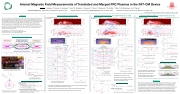
 Internal Magnetic Field Measurements of Translated and Merged FRC Plasmas in the FAT-CM Device
Abstract
Field-reversed configuration (FRC) Amplification via Translation – Collisional Merging (FAT-CM) experiments have recently commenced to study physics phenomena of collisions and merged FRC plasma states [1]. Two independently formed FRCs are translated into the confinement region of the FAT-CM device, collided near the midplane of the device with a relative speed of up to ~400 km/s, and a final merged FRC plasma state is achieved; this FRC collisional merging technique is essentially the same as in the C-2/C-2U experiments [2,3]. To measure magnetic field profiles of the translated and merged FRC plasmas, an internal magnetic probe array, developed/provided by TAE Technologies [3], has been installed in the midplane of the FAT-CM device. Initial magnetic field measurements indicate that both the translated and the merged FRC plasma states exhibit a clear field-reversal structure, which is qualitatively in good agreement with 2-D MHD simulations.
Single-Sided / Translated FRC
Collisional Merging FRCs: w/ nominal mirrors at ~2 kG
Collisional Merging FRCs: w/ weak mirrors at ~1 kG
[1] F. Tanaka et al., in 26th Int’l Toki Conf., P2-17 (2017).
[2] M.W. Binderbauer et al., Phys. Rev. Lett. 105, 045003 (2010). [3] H. Gota et al., Rev. Sci. Instrum. 83, 10D706 (2012).
R-Formation
V-Formation
Internal magnetic probe radial array in the mid-plane
Mirror coil
Theta-Pinch Coil
Magnetic probe linear arrays in formation & confinement
FRC formation, translation, collisional merging
Theta-Pinch Coil
-3.0 -2.0
(FRC collision phase)
(c) 40
30 20 10
FAT-CM Experimental Device
Confinement Region
Antenna
Additional mirror coils
H. Gota,1 J. Ishiwata,2 F. Tanaka,2 A. Hosozawa,2 T. Asai,2 Ts. Takahashi,2 J. Sekiguchi,2 T. Roche,1 T. Matsumoto,1,3 S. Dettrick,1 Y. Mok,1 M.W. Binderbauer,1 and T. Tajima1,3
1TAE Technologies, Inc., 19631 Pauling, Foothill Ranch, CA 92610, USA; 2College of Science and Technology, Nihon University, Tokyo 101-8308, Japan; 3Department of Physics and Astronomy, UCI, Irvine, CA 92697, USA
22nd High Temperature Plasma Diagnostics conference – San Diego, CA, April 16-19, 2018
Bz & Bt radial profile evolution (on mid-plane)
Bz & Bt radial profile evolution (on mid-plane)
(Standard FRC merging case)
Bz & Bt radial profile evolution (on mid-plane)
(Incomplete FRC merging case)
Temperature [eV]
Temperature [eV] TemperTaetumrepe[reaVtu]re [eV] TempTereamtuprera[etuVre] [eV] TempeTraetmurper[aetVur]e [eV] TempeTraetmurpee[reaVtu]re [eV] Temperature [eV] Temperature [eV] Temperature [eV]
Bounced off
FRC translation
Linear array
probe array, and gets reflected off at the mirror region.
Radial profile of the internal magnetic field Bz(r) clearly shows a field-reversed structure. Relatively strong toroidal magnetic field during translation has been observed.
Colliding near center
Incomplete merging (2 peaks)
t = 25 μs
t = 35 μs
(FRC collision phase)
t = 25 μs t = 40 μs
No field reversal
t = 30 μs t = 45 μs
(at quiescent phase)
Radial profiles of B & B fields z t = t 35 μs
t = 55 μs
Line-integrated density (1020 m-2)
Poloidal flux (mWb) Excluded-flux radius (m)
r (cm)
Confinement vessel
FAT-CM device at Nihon University in Japan (For details, see J. Sekiguchi’s poster – 10.56)
Time evolution of excluded-flux radius (from magnetic probe linear array)
Shorter-lived FRC due to internal probe radial array
(FRC quiescent phase)
Radial profiles of Bz & Bt fields FRCs are collided / merged near the midplane.
(a) weak mirror field case è incomplete merging t = 40 μs
t = 65 μs
(b) sufficient mirror field case è FRCs fully merged t = 55 μs
t = 85 μs
t = 80 μs
Internal magnetic probe radial array setup (installed in the device mid-plane)
• Hollow linear feedthrough / 30”-stroke actuator (probe can be fully retracted) • SS304 tube with end-cap (28” long, 0.165” OD, 2-mil wall)
• Boron Nitride jackets (0.25” OD, 35-mil wall)
• •
p 0 z R z (2) Rigid-rotor profile model
r3
f p _ RR » 0.31xs ΔΦ = 0.31p s Be
r w
Quasi-steady state confinement coil
-1.0 0 1.0
2.0
3.0 z(m)
Collision/merged FRC Single-sided FRC
0 -200
-150 -100 -50
0
50 100
150 200
0.2 0.1
0 2.0
1.5 1.0 0.5
0 2.0
(a)
(b)
(c)
z (cm)
Axial profile of excluded-flux radius
Smaller and shorter-lived FRC
Less poloidal flux estimated
2D MHD Lamy Ridge Simulations
1.5 1.0 0.5
0 0
50 100
150
Time (μs)
250
300
350
•
• Clear field-reversed structure in Bz(r)
•
• •
•
• •
FRCs are collided near the midplane, but not fully merged due to weak mirror field.
No field-reversed structure observed
2D MHD simulations show similar results of mirror-field effect in FRC merging.
Summary
Typical plasma parameters (w/o internal radial probe inserted)
• •
Strong B still remains after FRC merging. t
Poloidal flux can be estimated from Bz profile as well as using rigid-rotor model.
Internal Probe Radial Array – Specifications
Designed/developed by TAE Technologies, Inc [3] B-dot/pickup coils:
• Gold plated Tungsten wire with Kapton insulation
• ~1.5 mil W wire, insulated with ~0.3 mil Polyimide, final OD ~1.85 mil • 16 sets of Bz & Bt w/ 3 cm spacing
• y~ -10 – +35 cm coverage (wall radius ~40 cm)
Vacuum boundary & Plasma facing material:
Time evolution of excluded-flux radius (from magnetic probe linear array)
200
Radial array
Radial array
Linear array
rΔφ at 80 μs with Bmirror ~0.2 T Bmirror ~0.1 T
Radial profiles of Bz & Bt fields
• FRC plasma is translated into the confinement region, passing through the internal magnetic
Poloidal Flux Estimation
(rs~rDf)
FRC collisional-merging experiments have been started in the FAT-CM device to investigate physics phenomena of the single-sided/translated FRC as well as of the collision and the merging process of the two oppositely-directed/collided FRCs in the confinement region.
Initial experimental results of the internal magnetic field measurements indicated that both the translated and the merged FRC plasma states exhibited a clear field-reversed structure.
Confinement mirror field played an important role in attaining a good/adequate merging process by colliding two FRCs. The result is in good agreement with 2D MHD simulations.
Radial array
Linear array
(1) Bz profile
f = -òR 2prB dr = òrs 2prB dr
fp ~0.6 mWb fp_RR ~1.5 mWb
The discrepancy could be due to plasma radial motion.
| 1 |
